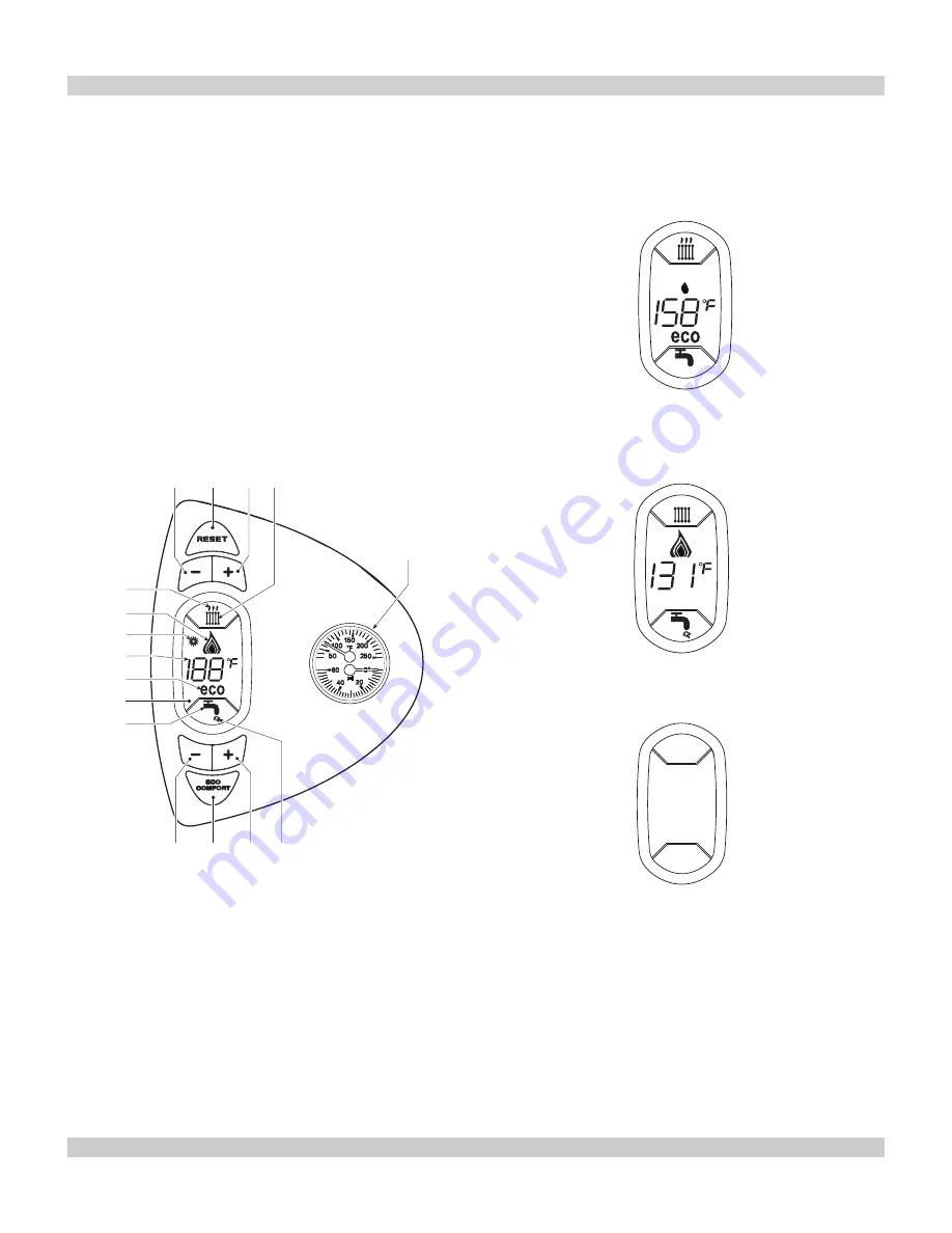
10.4 Control Panel
64
2
1
7
4
3
11
10
12
6
8
15
13
14
5
9
Key
1 =
DHW Temperature Setting Decrease Button
2 =
DHW Temperature Setting Increase Button
3 =
Heating System Temperature Setting Decrease Button - CH
4 =
Heating System Temperature Setting Increase Button - CH
5 =
Display
6 =
Summer/Winter Mode Selection - Reset Button
7 =
Unit On/Off - Economy/Comfort Mode Selection Button
8 =
DHW Symbol
9 =
DHW Mode
10 =
Summer Mode
11 =
Multifunction - Temperature
12 =
Eco (Economy) Mode
13 =
Heating
14 =
Heating Symbol
15 =
Burner On And Actual Power
64 =
C.H. Temperature Pressure Gauges
10.5 Indicator During Operation
Heating
Call for heat (generated by Room Thermostat) is indicated
by hot air
fl
ashing above radiator symbol on the control.
Hot water
If optional tank sensor is installed call for hot water is
indicated by hot water
fl
ashing under the tap on the control.
10.6 Turning on and off
NO electrical power to the boiler
The antifreeze system does not work when power and/or
gas to the unit are turned off. To avoid damage caused by
freezing during long idle periods in winter, it is advisable to
drain all water from the boiler, DHW circuit and system; or
drain just the DHW circuit and add a suitable antifreeze to
the heating system. See Section 5.3 page 11.
10 - OPERATING INSTRUCTIONS
10.3 Checks During Operation
• Boiler is arranged for connection to an external storage
tank for hot water production (optional). All functions
relevant to domestic hot water production are only
active with the optional water tank connected.
• Check for leaks in piping systems. Correct immediately
if found.
• Check the ef
fi
ciency of the
fl
ue gases and combustion
air ducts while the boiler is working.
• Check water is circulating between boiler and systems.
• Verify the gas valve modulates correctly in both
heating and hot water production phases.
• Check proper ignition of the boiler by turning it on and
off with the room thermostat.
• Check parameters are programmed correctly and
perform any required customization (compensation
curve, power, temperatures, etc.)
27
Summary of Contents for CHB-100
Page 6: ...Figure 2 Component Listing 6 3 GENERAL VIEW AND MAIN COMPONENTS ...
Page 33: ...33 12 RATINGS AND CAPACITIES ...
Page 38: ...KEY Part Number Description Qty A01 FE3980B830 CASING CTR 1 38 REPAIR PARTS LIST CHB 100 ...
Page 40: ...40 REPAIR PARTS LIST CHB 100 ...
Page 42: ...42 REPAIR PARTS LIST CHB 100 ...
Page 44: ...KEY Part Number Description Qty A01 FE3980B830 CASING CTR 1 44 REPAIR PARTS LIST CHB 130 ...
Page 46: ...46 REPAIR PARTS LIST CHB 130 ...
Page 48: ...48 REPAIR PARTS LIST CHB 130 ...
Page 50: ...NOTES 50 ...
Page 51: ...NOTES 51 ...
Page 52: ...ECR International Inc 2201 Dwyer Avenue Utica NY 13501 web site www ecrinternational com ...


