


21
ECOWATER
S Y S T E M S
Non-Wi-Fi Systems Only: Remote Operation
CHANGING THE ORDER OF DATA ITEMS
DISPLAYED IN THE STATUS SCREENS
In addition to changing which data items the remote dis-
plays during normal operation, the order of these items
may be customized, as follows:
1
. Press the remote’s LEFT (
3
) or RIGHT (
4
) buttons
to manually advance to the status screen you want to
customize. For example, to change the order of the
conditioner/refiner’s screen, manually advance to the
EWS 3500
status screen.
2
. Press the remote’s SELECT (
¡
) button to display the
device menu.
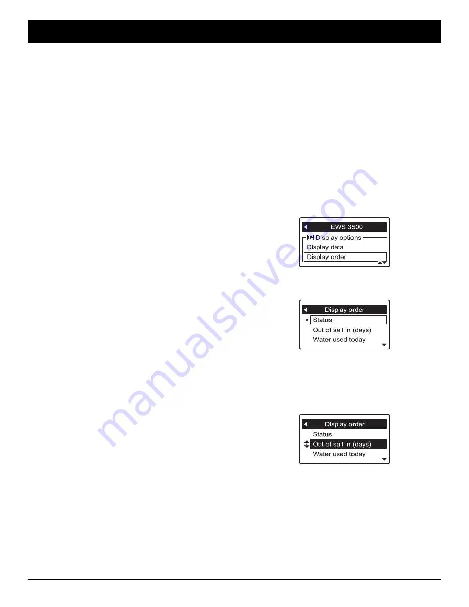
3
. Press the DOWN (
6
) button to scroll through the
menu options until
Display order
is highlighted in a
box (See Figure 66).
FIG. 66
4
. Press the SELECT (
¡
) button to display the Display
order screen (See Figure 67).
FIG. 67
FIG. 68
5
. Press the DOWN (
6
) or UP (
5
) buttons to scroll
through the list of display data items. Stop when the
item you want to move is highlighted in a box.
6
. Press the SELECT (
¡
) button. Arrows will appear
next to the item (See Figure 68).
7
. Press the UP (
5
) or DOWN buttons to move the
item higher or lower in the list.
8
. When the item is where you want it in the list, press
the SELECT (
¡
) button. The arrows next to the item
will disappear.
9
. To move another item, return to Step 5. When fin-
ished moving items, press the LEFT (
3
) button. The
display will go back to the device menu (Figure 66).
5
. Press the DOWN (
6
) or UP (
5
) buttons to scroll
through the list of display data items. Items with a
check mark in the box next to them will be displayed
during normal operation.
6
. To select an unchecked display data item, make sure
the box next to the item’s name is highlighted (box is
black inside). Then press the SELECT (
¡
) button.
The check mark will appear in the box.
7
. To un-select a checked display data item, make sure
the box next to the item’s name is highlighted (box is
black inside). Then press the SELECT (
¡
) button.
The check mark will disappear.
8
. When selections are complete, exit this menu by
pressing the LEFT (
3
) button. The display will go
back to the device menu (Figure 64).
9
. Press the LEFT (
3
) button to exit this menu, or wait
30 seconds for it to exit automatically.
OUT OF SALT IN (X) DAYS
This display, on both the conditioner/refiner and remote
status screens, is an
estimate
of the number of days
until the conditioner/refiner will be out of salt. This esti-
mate is based on salt level in the brine tank, salt dose
used, and average daily water use. It is recalculated
when the conditioner/refiner regenerates, and the num-
ber of days may decrease, remain the same or even
increase at regeneration time (a drop in water use could
cause the estimated days left to increase). Between
regenerations it will count down.
PHOTO CELL
To prolong battery life, the remote has a photo cell
above the display (See Figure 42). This cell triggers
the display to “go to sleep” (turn off) when the ambient
light level stays low for 10 minutes. The display will
immediately turn back on when the ambient light level is
increased.
NOTE:
The “Alert” LED (See Figure 42) will not “go to
sleep” if ambient light levels are low.


