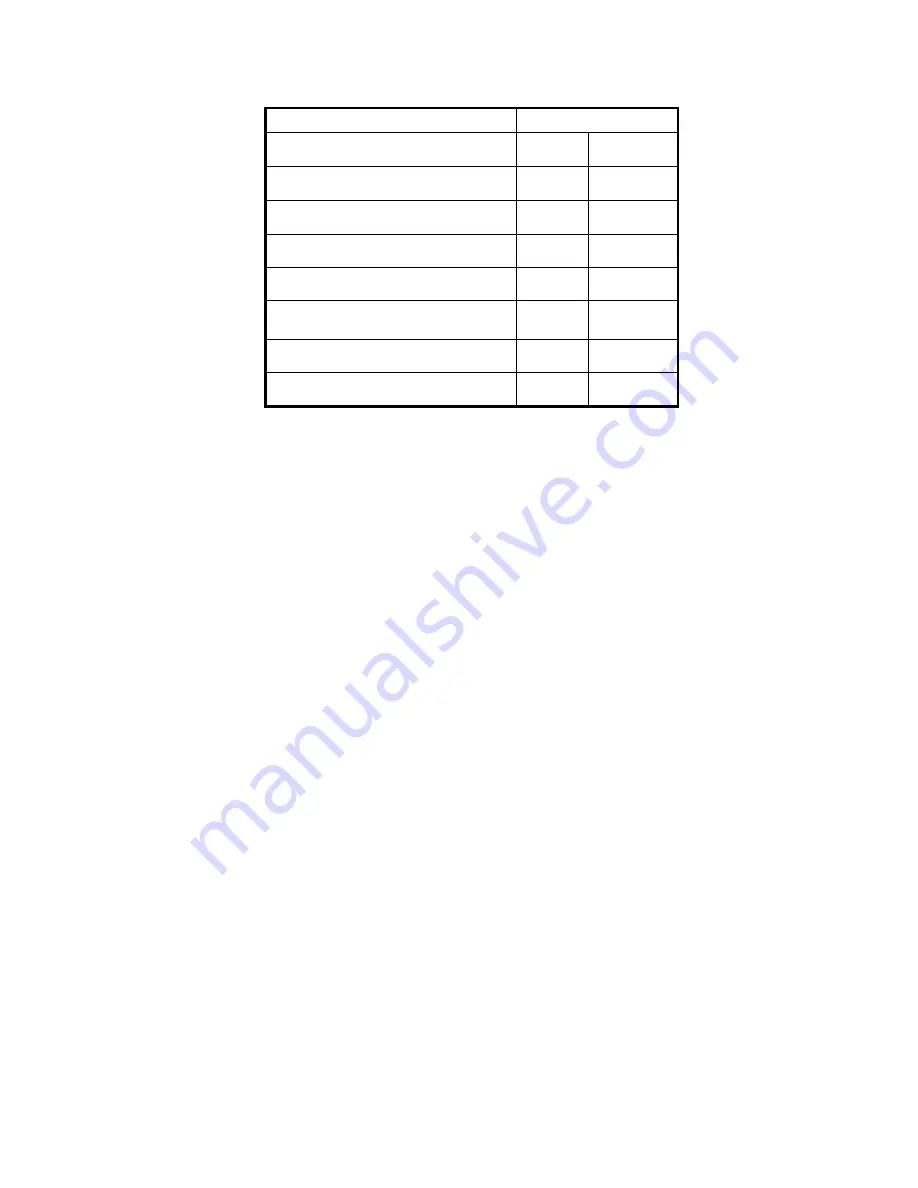
Ecotermal MODULE-T 10 kW Manual Download Page 16


16 


Tab. 6 


Note: The manufacturer reserves the right to make construction changing of the 
product. 


01.04.2014 


MODEL 

EQUIPMENT 

MRT 

Module Т 

Expansion tank 


Circulation pump 


Water filter 


Safety valve 


Blocking (emergency) 
Thermostat 


Air bleeder 


Mounting brackets 


Summary of Contents for MODULE-T 10 kW

Page 1: ...OF ELECTRIC BOILER WITH THREE STAGE ELECTRONIC CONTROL ECOTERMAL MRT MODULE T 6 8 10 12 15 22 30 kW Bourgas 8000 47 Slivnitsa str tel 056 814 681 056 814 215 fax 056 814 584 Sofia 1000 Druzhba 1 Comp...

Page 2: ...8 7 Commissioning 8 8 Conditions of commissioning and undertaking guarantee maintenance 8 9 9 Diagrams and tables 10 15 9 1 Method of connecting of story local heating Fig 1 10 9 2 Method of connecti...

Page 3: ...hereof In case of failure contact the service organization Unprofessional intervention may damage the boiler For correct functioning safety and long term operation secure prophylactics at least once a...

Page 4: ...This signal is in the 4 20 mA range Because both the regulators room and boiler are interconnected in cascade system this signal goes as a setpoint at the boiler thermo regulator s input which in tur...

Page 5: ...thermo regulator In this case jumper J1 which placed on the main board is switched to pos 2 and by trimmer potentiometer W pos 12 the temperature is set In all other cases jumper J1 is placed in pos...

Page 6: ...hree phases of the contactors for power pos 13 Relays are connected to six power wires X6 in scheme with a total zero H7 is connected to contact external clock for timing of operation of the boiler in...

Page 7: ...ble controller is placed If a thermostatic valve is installed in the same room it should be fully open in order not to prevent the normal operation of the programmable thermo regulator The water tempe...

Page 8: ...tion diagram The cross section of the power supply cable should be selected in accordance with the boiler power see Table 4 page 14 7 COMMISSIONING Boiler startup is possible after performed control o...

Page 9: ...ce with the attached manufacturer s instructions 4 The boiler should not be contaminated with building materials 5 Banjo fitting connections should be mounted on the boiler intake and the outlet 6 Hyd...

Page 10: ...erature 7 Return valve 2 Air bleeder 8 Water filter 3 Shut off valve 9 Safety valve by pressure 4 Electric heater 10 Solid fuel boiler 5 Electric boiler 11 Expansion vessel 6 Circulation pump 12 Manif...

Page 11: ...p 6 Water filter ELECTRICAL BOILER MRT 6 30 kW 1 Frame 2 Safety Valve 2 5 bar 4 Automatic Breaker 5 Emergency blocking Thermostat 6 Air Bleeder 7 Control Module 8 Water Container 9 Pressure gauge 10 H...

Page 12: ...2 Fig 3 MODULE T 6 30 KW 1 Frame 2 Safety Valve 2 5 bar 4 Automatic Breaker 5 Emergency blocking Thermostat 6 Air Bleeder 7 Control Module 8 Water Container 9 Pressure gauge 10 Heaters 12 Control Pane...

Page 13: ...tion First Stage ON 3 LED Indication of activated emergency thermostat 4 LED Indication of circulation pump condition 5 Button set current temperature 6 Pressure gauge 7 Potentiometer of boiler s temp...

Page 14: ...width mm 260 Module T 6 30 kW 6 30 height mm 645 length mm 315 width mm 270 Maximum power kW 6 8 10 12 15 22 30 Comutations level N 3 3 3 3 3 Boiler body volume dm3 8 9 8 9 8 9 8 9 8 9 Supply voltage...

Page 15: ...1 11 5 x 2 5 16 10 13 89 3 x 2 5 1 5 1 4 20 12 16 67 3 x 4 2 5 1 4 25 15 20 83 3 x 4 2 5 1 6 32 22 31 25 3 x 6 4 1 10 50 30 41 67 3 x 10 6 1 10 63 Electrical boilers Electrical modules Model Power kW...

Page 16: ...turer reserves the right to make construction changing of the product 01 04 2014 MODEL EQUIPMENT MRT Module Expansion tank Circulation pump Water filter Safety valve Blocking emergency Thermostat Air...

Reviews: