12
Fig.3
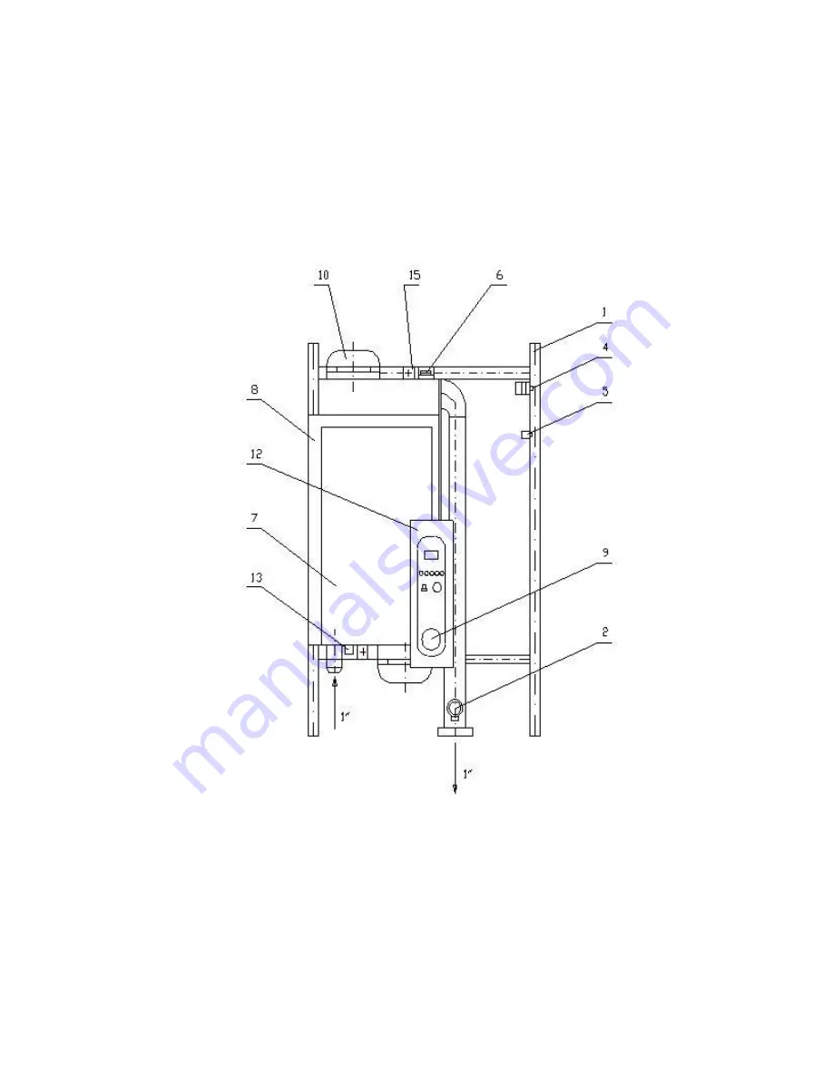
MODULE T 6 – 30 KW
1. Frame
2. Safety Valve 2.5 bar–½” 4. Automatic Breaker 5. Emergency (blocking) Thermostat 6. Air Bleeder
7. Control Module 8. Water Container
9. Pressure-gauge
10. Heaters
12. Control Panel
Page 1: ...OF ELECTRIC BOILER WITH THREE STAGE ELECTRONIC CONTROL ECOTERMAL MRT MODULE T 6 8 10 12 15 22 30 kW Bourgas 8000 47 Slivnitsa str tel 056 814 681 056 814 215 fax 056 814 584 Sofia 1000 Druzhba 1 Comp...
Page 2: ...8 7 Commissioning 8 8 Conditions of commissioning and undertaking guarantee maintenance 8 9 9 Diagrams and tables 10 15 9 1 Method of connecting of story local heating Fig 1 10 9 2 Method of connecti...
Page 3: ...hereof In case of failure contact the service organization Unprofessional intervention may damage the boiler For correct functioning safety and long term operation secure prophylactics at least once a...
Page 4: ...This signal is in the 4 20 mA range Because both the regulators room and boiler are interconnected in cascade system this signal goes as a setpoint at the boiler thermo regulator s input which in tur...
Page 5: ...thermo regulator In this case jumper J1 which placed on the main board is switched to pos 2 and by trimmer potentiometer W pos 12 the temperature is set In all other cases jumper J1 is placed in pos...
Page 6: ...hree phases of the contactors for power pos 13 Relays are connected to six power wires X6 in scheme with a total zero H7 is connected to contact external clock for timing of operation of the boiler in...
Page 7: ...ble controller is placed If a thermostatic valve is installed in the same room it should be fully open in order not to prevent the normal operation of the programmable thermo regulator The water tempe...
Page 8: ...tion diagram The cross section of the power supply cable should be selected in accordance with the boiler power see Table 4 page 14 7 COMMISSIONING Boiler startup is possible after performed control o...
Page 9: ...ce with the attached manufacturer s instructions 4 The boiler should not be contaminated with building materials 5 Banjo fitting connections should be mounted on the boiler intake and the outlet 6 Hyd...
Page 10: ...erature 7 Return valve 2 Air bleeder 8 Water filter 3 Shut off valve 9 Safety valve by pressure 4 Electric heater 10 Solid fuel boiler 5 Electric boiler 11 Expansion vessel 6 Circulation pump 12 Manif...
Page 11: ...p 6 Water filter ELECTRICAL BOILER MRT 6 30 kW 1 Frame 2 Safety Valve 2 5 bar 4 Automatic Breaker 5 Emergency blocking Thermostat 6 Air Bleeder 7 Control Module 8 Water Container 9 Pressure gauge 10 H...
Page 12: ...2 Fig 3 MODULE T 6 30 KW 1 Frame 2 Safety Valve 2 5 bar 4 Automatic Breaker 5 Emergency blocking Thermostat 6 Air Bleeder 7 Control Module 8 Water Container 9 Pressure gauge 10 Heaters 12 Control Pane...
Page 13: ...tion First Stage ON 3 LED Indication of activated emergency thermostat 4 LED Indication of circulation pump condition 5 Button set current temperature 6 Pressure gauge 7 Potentiometer of boiler s temp...
Page 14: ...width mm 260 Module T 6 30 kW 6 30 height mm 645 length mm 315 width mm 270 Maximum power kW 6 8 10 12 15 22 30 Comutations level N 3 3 3 3 3 Boiler body volume dm3 8 9 8 9 8 9 8 9 8 9 Supply voltage...
Page 15: ...1 11 5 x 2 5 16 10 13 89 3 x 2 5 1 5 1 4 20 12 16 67 3 x 4 2 5 1 4 25 15 20 83 3 x 4 2 5 1 6 32 22 31 25 3 x 6 4 1 10 50 30 41 67 3 x 10 6 1 10 63 Electrical boilers Electrical modules Model Power kW...
Page 16: ...turer reserves the right to make construction changing of the product 01 04 2014 MODEL EQUIPMENT MRT Module Expansion tank Circulation pump Water filter Safety valve Blocking emergency Thermostat Air...