background image

17

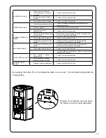
By pressing the button P3 on the display the alarm can be reset.  Try and repeat lighting after the 

cooling phase.

FAN BROKEN ALARM

•  Smoke extractor encoder is 

not functioning or not correctly 

connected

• 

Contact local Service Technician

•  No electricity supply to smoke 

extractor

• 

Contact local Service Technician

•  The smoke extractor is blocked

• 

Contact local Service Technician

DEPRESSION ALARM

•  The combustion chamber is dirty

•  Follow the cleaning operations of the stove as per the 

instructions manual

•  The flue is blocked

•  Check that the flue is clear and clean

•  The vacuum switch is 

malfunctioning

• 

Contact local Service Technician

THERMAL ALARM WITH 

RESET

•  The thermostat with manual reset 

has intervened

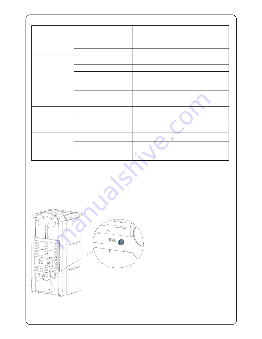
•  Reset the thermostat pressing the button on the back of the 

stove (see Figure below this table)

•  The centrifugal fan is defective

• 

Contact local Service Technician

•  Combustion in the fire pot is not 

optimal

•  Switch off the stove, clean the fire pot and regulate 

combustion with the setting of the pellets

HOT SMOKE ALARM

•  Combustion in the fire pot is not 

optimal

•  Switch off the stove, clean the fire pot and regulate 

combustion with the setting of the pellets

•  The centrifugal fan is defective

• 

Contact local Service Technician

• 

IF THE PROBLEM CONTINUES, CONTACT YOUR LOCAL 

SERVICE TECHNICIAN.

SMOKE SENSOR ALARM

•  The 

smoke 

sensor 

is 

malfunctioning

• 

Contact local Service Technician

•  The smoke sensor has been 

disconnected from the board

• 

Contact local Service Technician

AUGER BLOCKED 

ALARM

•  The auger does not load pellets

• 

Contact local Service Technician

Unscrew  the  protection  cap  and  press 

the button to reset the thermostat alarm.

Summary of Contents for Monica Plus

Page 1: ...HIS PELLET BURNING ROOM HEATER FAILURE TO FOLLOW THESE INSTRUCTIONS COULD RESULT IN PROPERTY DAMAGE BODILY INJURY OR EVEN DEATH Contact your local building or fire official about restrictions and installation inspection requirements in your area economical user friendly leading design healthy home visible flame clean air approved ...

Page 2: ...tion of the Controls 8 2 2 Description of Remote control 8 2 3 Switching on the Stove 8 2 4 Operating Precautions 8 2 5 Priming of the Screw Auger 8 2 6 Description of Menus 9 2 7 Setting the Clock Clock Set Menu 10 2 8 Chronothermostat Setting Menu 10 2 9 Setting the Language Language Menu 14 2 10 Settings Menu 14 2 11 Description of the functions 14 2 12 Mode with Room Sensor Supplied 14 2 13 Ex...

Page 3: ...bustion chamber 20 3 5 Cleaning the Flu 20 3 6 Access to the inspection hatches for cleaning the smoke 21 3 7 Frequency of Component Cleaning 21 3 8 Cleaning the Ashes Draw 22 4 Guarantee 23 4 1 Certificate of Guarantee 23 4 2 Conditions of Guarantee 23 5 What are Wood Pellets 24 6 The Components of the Stove 24 ...

Page 4: ... 150mm in front for ember protection AS NZS2918 states that a 300mm forward projecting and 200mm side projecting floor protector must be used from any door opening extremity as an absolute minimum Due to the operating nature of the Monica Plus pellet heater where opening the door causes a loss of vacuum and the fire will shut down completely meaning the likelihood of any hot embers or burning fuel...

Page 5: ... a bedroom or room where people sleep 2 Locate the pellet heater in a large and open room that is centrally located in the house This will optimize heat circulation 3 Check clearances to combustibles refer page 30 2 2 Ash The ash content of the fuel and operation of your stove will directly determine the frequency of cleaning The use of high ash fuels may result in the stove needing to be cleaned ...

Page 6: ...lue joins must be sealed with maniseal exhaust cement The protection grill inside the pellet tank must never be removed There must be sufficient circulation of air in the room where the stove is installed Never open the door of the stove whilst it is functioning When the heater is operating the surfaces the glass the handle and the pipes become overheated during functioning these parts must only b...

Page 7: ... the display The details can be seen in the chapter on the alarms page 16 2 9 Responsibility Nature s Flame declines all responsibility both civil and criminal with the delivery of this manual for any accidents deriving from partial or total failure to observe the instructions it contains Nature s Flame declines all responsibility deriving from the improper use of the stove from its incorrect use ...

Page 8: ...of unburned pellets inside the fire pot after repeatedly trying to light the stove must be removed before further attempts Do not use any fuels other than wood pellets Should the ignition system be faulty do not attempt to light the stove using flammable materials 3 5 Priming of the Screw Auger To prime the screw auger when the stove is new or has been completely run out of fuel the loading 20 C 1...

Page 9: ...hese menus are accessible by the user others are protected by a password and accessible only by a Service Technician The menus are as follows CLOCK SETTING Menu CHRONO THERMOSTAT Menu LANGUAGE Menu SETTINGS Menu STOVE STATUS Menu WORKING HOURS Menu DATA BASE Menu protected by a password 2000 150 SCREW 0 STATE THE SCREW IS IDLE PRESS BUTTON P5 TO ACTIVATE THE SCREW AUGER 2000 150 SCREW 1 STATE SCRE...

Page 10: ...rm with button P6 to return automatically to MENU 01 CLOCK SETTING 3 8 Chronothermostat Setting Menu With the chronothermostat function switching on and off the stove for each day of the week can be programmed in two independent time intervals PROGRAMME 1 and PROGRAMME 2 To enter this menu proceed as follows 1 Keep button P4 pressed for 2 seconds CLOCK SETTING MENU will appear 2 Press button P4 on...

Page 11: ... go to next programme POWER PROG This parameter shows the power the stove is set to when starting with CRONO SET TAMB PROG This parameter shows the ideal temperature you want to be reached in the room where the stove is installed when starting with CRONO on This setting will have priority over the manual setting Description Values that can be set START PROG 1 From OFF to 23 50 with step of 10 STOP...

Page 12: ...5 Press button P6 to confirm and continue with next screen In the case of error press P7 to go back one step 08 30 PROG 1 STOP Set the time desired for PROGRAM 1 to turn off with buttons P4 and P5 Press button P6 to confirm and continue with next screen ON 1 PROG 1 MONDAY Set the day on which we want PROGRAM 1 to be active or not active with button P5 in this case Monday At this point set the valu...

Page 13: ...NG THIS MODE YOU HAVE TO MAKE SURE THAT EACH TIME THE STOVE IS AUTOMATICALLY SWITCHED OFF THE FIRE POT REMAINS CLEAN IN ORDER TO GUARANTEE CORRECT AUTOMATIC IGNITION Carry out the same operations changing times and days of activation for PROG 2 as well After we select the power we have to decide on the desired room temperature independently from the temperature we set during manual start up settin...

Page 14: ...isplay the parameters set 5 Scroll till last parameter to return automatically to MENU 04 SEE SETTINGS MENU 3 11 Modifications of the room temperature setting The modes of functioning of the stove with the ambient thermostat activated can be divided into two types with room sensor supplied not available on INSERTS positioned on the back of the stove with external thermostat not supplied 3 12 Mode ...

Page 15: ...y a service technician to diagnose performance issues and for the customer when loading pellets into the pellet hopper when the stove has been completely run out of fuel 3 15 Working Hours Menu The WORKING HOURS Menu shows the total hours of work done by the stove In some cases the working hours may not be zeroed i e numbers similar to 5000 15000 25000 may be shown The technician will zero set the...

Page 16: ...S PLEASE CONTACT A SERVICE TECHNICIAN WARNING REASON SOLUTION PELLETS FINISHED ALARM The pellet hopper is empty Check whether there are pellets in the hopper and refill if necessary The raio motor does not load pellets Empty the hopper to check that no foreign objects have fallen inside which could prevent the correct functioning of the auger Pellets not loading Regulate the pellet setting IF THE ...

Page 17: ... thermostat pressing the button on the back of the stove see Figure below this table The centrifugal fan is defective Contact local Service Technician Combustion in the fire pot is not optimal Switch off the stove clean the fire pot and regulate combustion with the setting of the pellets HOT SMOKE ALARM Combustion in the fire pot is not optimal Switch off the stove clean the fire pot and regulate ...

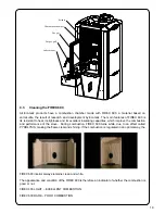
Page 18: ... combustion takes place is clean and that no waste or residue blocks the holes in order to always guarantee excellent combustion of the stove This will help avoid possible overheating which could causes changes in the colour of the paint as well as failure to light the stove Only a clean fire pot can guarantee that the pellet stove will function without problems During functioning deposits may be ...

Page 19: ...e the combustion and performance of the stove During combustion FIREX 600 turns white due to an effect called PYROLYSIS making the flame clear and shining If the combustion is regulated in an optimal way the FIREX 600 interior always remains clean and white The appearance and condition of the FIREX 600 is therefore an indicator of whether the combustion is good or not FIREX 600 LIGHT EXCELLENT COM...

Page 20: ...n how maintenance is carried out The pellet stove is a generator of heat with a solid fuel and as such requires servicing by qualified personnel at least once a year at the start of the season This maintenance has the purpose of ascertaining and ensuring the efficiency and safety of all the components We recommend you draw up an annual contract for maintenance of the product with your installer de...

Page 21: ...um type vacuum cleaner 4 7 Frequency of Component Cleaning INSPECTION HATCH 2 ON THE RIGHT SIDE INSPECTION HATCH 1 ON THE LEFT SIDE GASKET GASKET GASKET SCRAPER Parts Frequency 1 Day 2 3 Days 30 Days Yearly Performed By Burn pot Owner Burn pot grill Owner Glass Owner Flu Technician Door gasket Technician Heat Exchanger Owner Combustion chamber Owner Vacuum Hopper Owner Clean T discharge Technician...

Page 22: ...d To access the drawer open the door see figure 1 and extract the ashes drawer see figure 2 N B The operation must be carried out when the stove is cold using a drum type vacuum cleaner HOW TO REMOVE THE FLAME TRAP N B REMOVE AND CLEAN THE FLAME TRAP REGULARLY 1 2 FRONT FLAME TRAP REST REAR FLAME TRAP REST Phase B Phase A POSITION OF THE FRAME TRAP SLOT ...

Page 23: ...sness wrong connections or errors of installation The following are not covered by guarantee vermiculite Firex 600 the glass of the door the fibre gaskets the painting the stainless steel combustion basket the resistance the cast majolica any damage caused by inappropriate installation and or handling of the stove and or shortcomings by the consumer The use of poor quality pellets or of any other ...

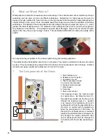
Page 24: ...ts during the loading operations The pellets must be transported and stored in a dry place They swell on contact with damp and cannot be used They must always be protected from the damp both during transport and in storage Ecoteck recommends using a pellet with a diameter of 6 mm for the stove 7 The Components of the Stove 7 2 3 6 1 8 9 5 4 9 1 Pellet loading screw 2 Resistance unit for ignition 3...

Page 25: ...ions 29 2 3 Minimum Clearance to Combustibles 30 2 4 Location of the Pellet Fire 30 2 5 Positioning the fire 30 2 6 Location of a power source 30 2 7 Internal Standard Flue Kit 50 31 2 8 External Standard Flue Kit 51 32 2 9 Seismic Restraint 33 2 10 Fixing to Timber Floor Framing 33 2 11 Installation 33 2 12 How to remove the side panels 34 2 13 Seismic Restraint Locations 35 3 Installation Data S...

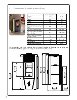
Page 26: ...rement Height mm 1037 Width mm 508 Depth mm 476 Weight Kg 130 Diameter of smoke exhaust duct mm 80 Min max calorific power kW 5 0 6 5 Min max hourly consump tion of pellets Kg h 0 99 1 43 Electrical power absorbed during operation W 240 Supply V Hz 220 50 Tank capacity Kg 15 Space Heating Efficiency 85 0 771mm 30 33in 385mm 15 16in 190mm 7 48in 599mm 23 59in 43mm 1 69in 459mm 18 07in 1037mm 40 81i...

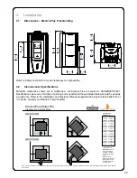
Page 27: ...be used from any door opening extremity as an absolute minimum Due to the operating nature of the Monica Plus pellet heater where opening the door causes a loss of vacuum and the fire will shut down completely meaning the likelihood of any hot embers or burning fuel escaping from the combustion chamber is extremely minimal Therefore a 150mm forward projecting floor protector will be sufficient Hea...

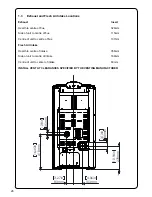
Page 28: ...flue 115mm Centre of unit to centre of flue 137mm Fresh Air Intake Hearth to centre of intake 356mm Side of unit to centre of intake 169mm Centre of unit to center of intake 83mm INSTALL VENT AT CLEARANCES SPECIFIED BY THE VENTING MANUFACTURER 80mm 3 13in 83mm 3 27in 103mm 4 06in 278mm 10 94in 418mm 16 45in 35mm 1 38in ...

Page 29: ...tion and Operation Manual supplied with every Ecoteck Pellet Fire or if in doubt consult your Nature s Flame Retailer B J H A E External Flue J J F B I F E Monica Plus Pellet Fire Clearance to Combustibles B C A E D G F B F G E Internal Flue Location Dimension mm A 50 B 150 C 50 D 230 E 100 F 120 G 50 H 50 I 50 J 25 Freestanding Clearances from shielded flue Note AS NZS 2918 requires a minimum of ...

Page 30: ...through tubes in the direction that the fire faces for optimum performance this location should be in a large room centrally located Monica Plus must be installed on a non combustible surface This surface must protrude 150mm from the front of the closed pellet fire door Monica Plus has been Safety Tested to AS NZS 2918 using the Davins manufactured flue Test Report ARS 05 1185 Installation is not ...

Page 31: ...ing plate is white T he support angles for securing the liner to the ceilin g are not shown Kit is supplied in a carton Heat resistant floor protector Seismic restraint to be fitted 50mm minimum clearance if lined flue 600mm from roof penetration 210mm 150mm minimum Note The Davin 50 Internal Standard Flue Kit complies with AS NZS 2918 2001 as per Applied Research Test Report 05 1185 dated 15 Sept...

Page 32: ... supplied in a carton Note The Davin 51 External Standard Flue Kit complies with AS NZS 2918 2001 as per Applied Research Test Report 05 1185 dated 15 September 2005 All fires must be installed by a qualified installer as per the manufacturer s instructions and AS NZS2918 2001 Heat resistant floor protector Seismic restraint to be fitted 600mm from roof penetration 100mm minimum 150mm minimum Exte...

Page 33: ... Installation Monica Plus should be installed in a centrally located position within the home This will assist the appliance to perform to the level required As Monica Plus heats space by convecting air through heat exchange tubes the heater should face the area the majority of the area to be heated Monica Plus requires a power source to function This is standard mains feed 240v plug if this is un...

Page 34: ...let lid SPACERS SPACERS Insert the ceramic tiles in the side guide inserting the rubber spacers as illustrated in the figure Mount the ceramic top on the top of the stove To adjust the height of the top adjust the four screws make sure that the screws have their rubber cap At the end remount to the pellet lid Rubber Cap ...

Page 35: ...35 2 13 Seismic Restraint Locations INSPECTION HATCH 2 ON THE RIGHT SIDE GASKET GASKET INSPECTION HATCH 1 ON THE LEFT SIDE SEISMIC RESTRAINT LOCATION SEISMIC RESTRAINT LOCATION ...

Page 36: ..._______________ Phone ________________________________ Model ___________________________ Serial Number _____________________ Date of Purchase ___________ dd mm yy Date of Installation __________ dd mm yy Magnehelic at Install ________________ Installer s Signature ________________________________ Name of Installer ________________________________ Address ________________________________ __________...

Page 37: ...37 4 Maintenance Record DATE WORK CARRIED OUT SIGNATURE ...

Reviews: