background image

2

eCopy ScanStand Assembly Instructions

Alternative arm positions

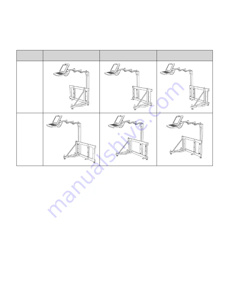
You can position the arm support post on any one of the three vertical struts on the rear frame. For example, if a 
paper reservoir is present at the side of the copier, you can position the post on the middle vertical strut so the 
screen and keyboard are closer to the copier's control panel.

In rare situations, you may need to position the post and arm assembly at the opposite end of the rear frame 
from the angle frame. The diagrams below illustrate various configuration options.

Typical configuration

Configuration to accommodate 

reservoir or other large accessory

Rarely used but available if 

required

Right 
configuration

Left 
configuration

Summary of Contents for ScanStand

Page 1: ... eCopy Inc All trademarks are properties of their respective owners see product documentation for details P N 73 00030 2 2006 eCopy ScanStandTM Assembly Instructions Revision 2 1 ...

Page 2: ... any means electronic or mechanical including photocopying recording or information storage and retrieval systems or translated into any language for any purpose other than the purchaser s personal use without the written permission of eCopy Inc 1992 2005 eCopy Inc eCopy the eCopy logo eCopyFax the Simplify logo the MailRoom logo eCopy ShareScan OP eCopy ScanStation eCopy ScanStation OP eCopy Desk...

Page 3: ...inisher is on the right of the copier configure the PC and arm at the left of the assembly Leave 6 9 inches 15 23 cm of clearance between the ScanStation and the copier access door Variations to these standard configurations are possible to accommodate paper reservoirs or other accessories see next page You can also place the PC behind the copier as shown below Typical configuration for finisher o...

Page 4: ... post on the middle vertical strut so the screen and keyboard are closer to the copier s control panel In rare situations you may need to position the post and arm assembly at the opposite end of the rear frame from the angle frame The diagrams below illustrate various configuration options Typical configuration Configuration to accommodate reservoir or other large accessory Rarely used but availa...

Page 5: ...mbly Instructions 3 Component identification A Touch screen B Keyboard C Arm D Rear frame E Arm support post F PC cover G L bracket H PC clamp I Master fastener kit J Angle frame Note Angle frame J ships inside PC cover F ...

Page 6: ... Friday 6 00 A M to 5 30 P M EST Phone 1 603 881 4450 select option 8 E mail support ecopy com Outside North America Please contact your local dealer or national sales organization The Master Fastener Kit contains four smaller kits Do not open the smaller kits until you are ready to use them Each kit is used in a separate step in the assembly process ...

Page 7: ...ons 5 Fastener Kit 1 P N 16 5001 A Components shown full size to help identification 1 1 Screw feet into threaded holes in underside of rear frame 2 and angle frame 1 Screw feet in all the way Feet 3 Step 1 Rear and angle frame assembly ...

Page 8: ...ft configuration front view Right configuration front view 1 3 Put a washer on each 50 mm 2 inch hex bolt and insert bolts through non threaded holes in back of frame and into threaded holes in angle frame Left configuration rear view Right configuration rear view 1 4 Tighten bolts securely using 13 mm wrench Do not over tighten or you will bend the metal tubing Rear and angle frame assembly conti...

Page 9: ...h 45 mm 1 3 4 inch hex bolt 2 3 From back of frame insert bolts through top and bottom holes in selected strut 2 4 Place L bracket on bolts and attach loosely using hex nuts 2 5 Slide bracket to lowest position You will re position and tighten the L bracket later Before you attach the L bracket determine which vertical strut you will use for the arm support post and attach the L bracket to an unus...

Page 10: ...m support post over bolt heads flat side against rear frame fitting the two bolt heads into the T slot on the post Tip While holding post with one hand rotate bolt heads to align edges parallel to T slot 3 4 Position post at desired height Typically the bottom of the post is aligned with the top edge of the rear frame s lower cross member 3 5 Tighten nuts securely using 13 mm wrench Frame Bottom o...

Page 11: ... with the eCopy logo Bolt heads should be on flat side of bracket 4 3 Place a washer and round head nut on each bolt Turn only 2 3 times leaving bolt heads extended at least 16 mm 5 8 inch from arm bracket 4 4 With arm folded align bolts heads as shown below and slide bolts into T slot on flat side of post Note bolt head alignment and required gap 4 5 Tighten the nuts securely using 13 mm wrench D...

Page 12: ...Allen screws 2 from underside of keyboard bracket and set screws aside Do not remove the tension screws 5 3 Slide tongue at rear of keyboard into keyboard bracket aligning the screw holes 5 4 Insert screws through back plate and into threaded holes in keyboard bracket Tighten securely 5 5 Flip keyboard down to horizontal position Bracket tension screw Step 5 Keyboard attachment ...

Page 13: ...ou may need to loosen the upper bracket tension screw first using the Allen key 6 2 Remove four pan head Phillips screws 4 from center back side of touch screen 6 3 Position the touch screen over the screen bracket Then re insert and tighten the four screws Step 6 Touch screen attachment ...

Page 14: ...s shown Leave approximately 50 mm 2 inches of slack in cables between screen and first clip 7 3 Pull cables tightly against side of arm joints and clip to remaining arm segments to maximize cable length 7 4 Guide cables over top of bracket and into vertical cable channel at rear of arm support post 7 5 Exit cables at or near base of post Step 7 Cable attachment ...

Page 15: ...otential for printing interruptions if the ScanStation is powered off B If there is no free network jack i Remove copier s network cable from wall jack and connect it to left port on PC s internal 3 port hub ii Connect supplied long Ethernet cable from network wall jack to uplink port on right of internal 3 port hub iii Connect supplied short Ethernet cable from middle port of internal 3 port hub ...

Page 16: ...the clips Warning Be careful to avoid pinching your hands between the cover and the frame 9 3 Push cover down and into position The locking tab should protrude from the top of the cover 9 4 Loosen nuts on L bracket and slide bracket up to contact underside of copier Tighten nuts securely using 13 mm wrench 9 5 Fold arm so front edge of keyboard lines up with front edge of copier 9 6 Readjust cable...

Reviews: