background image

ecom-EN3


Page 23


2


3


4.1.1 


Adaptation of the displays for gas analysis


Hint


The position of the measured and calculated values (gas analysis sub-menu) 
on the display pages is free selectable


For alteration of the existing succession, proceed as follows: 


- Press <Enter> / „Display values“ / <Enter> to activate the function


- Select line with cursor keys (Up/Down)


- Select desired parameter with cursor keys (Right/Left)


- Repeat procedure until desired layout is completed


- Press <Enter> to deactivate the function


4.1.2 


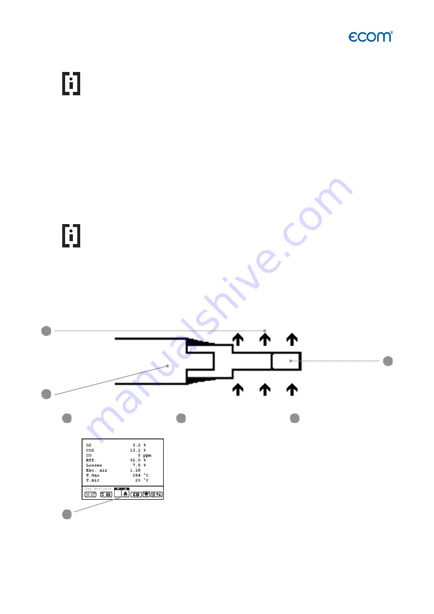
Positioning the probe, search the core stream


Hint


The correct positioning of the probe in the gas stream is necessary in order to 
achieve an impressive measuring result.


To correctly position the probe in the gas stream, proceed as follows:


- Connect the probe hose to the device "connection gas temperature"


- Position the sampling probe in the exhaust channel, so that the thermocouple is fully 

surrounded with the gas (see drawing).


Gas stream 

Protection bow 

Probe tip


Core stream search


Position the sampling probe in the exhaust channel 


(Position in the hottest gas temperature area).


Observe trend for T.Gas in the measurement display.


As  long  as  the  display  shows  an  arrow  in  upwards 
direction,  the  measured  temperature  increases,  it  means 
the probe tip moves towards the core stream center.


If an arrow in downwards direction is displayed, it means you move the probe away from the 
core stream and the temperature sinks.


1


2


1


3


Summary of Contents for EN3

Page 1: ...Operating Instructions The ecom EN3 meets the requirements of the DIN EN 50379 Part 2 ...

Page 2: ...P This manual is intended exclusively for authorized professionals Symbols DANGER Indicates that material damage can occur Indicates how the hazard can be avoided In both cases it is stated how the danger can be avoided Hints Hints are marked with an information symbol Text sections marked with an arrow call for an action WARNING Adjustments at burners and boilers should be made only by specialist...

Page 3: ...ction of the measuring instrument Make sure that the measuring instrument is not exposed to strong electromagnetic radiation sources DISPOSAL Dispose the packaging material of the instrument in an environmentally sound manner Old electrical equipment must be disposed in an environmentally sound manner by an authorized body On request we take back your old instrument purchased from us and guarantee...

Page 4: ...a grounded component eg water pipes radiators etc WARNING Electric shock Current carrying components at open housing Before opening the instrument housing disconnect the instrument from the mains supply at all poles WARNING The instrument is operated with a Li Ion battery The replacement of the battery must be carried out only by qualified personnel or by an ecom authorized service center ...

Page 5: ...ecom EN3 Page 5 ...

Page 6: ... 22 4 1 Gas analysis 22 4 1 1 Adaptation of the displays for gas analysis 23 4 1 2 Positioning the probe search the core stream 23 4 1 3 Printing measured values 24 4 1 4 CO Overload Protcektion 25 4 2 Measurement procedure gas analysis CO measurement 26 4 3 Measurement procedure gas analysis O2 Check 27 4 4 Measurement procedure gas analysis Draught measurement 27 4 5 Measurement procedure gas an...

Page 7: ...ection to PC 58 10 3 1 Data recording with PC Software ecom DAS NT 2 58 10 3 2 Data recording with PC Software ecom DAS 5 59 10 3 3 Data recording with PC Software Import and Export of Data 60 10 4 Data recording with App via WiFi 61 10 5 Data recording with App via BLE 62 11 Maintenance Tips 63 11 1 Fine dust filter 63 11 2 Gas sensors 64 11 3 Probe and tubing 64 11 4 Printer paper 65 11 5 Air le...

Page 8: ...dia card SD 4 Connection USB 5 Connections for Pa pressure sensor 6 Connection pressure 7 Battery and sensors compartment 8 Connection sampled gas 9 Connection draught 10 Condensation trap with peltier cooler with fine dust filter 11 Connection gas temperature 12 Connection air temperature 13 Integral thermal printer 14 Connection AUX 1 2 3 4 5 6 7 8 9 10 11 12 13 14 ...

Page 9: ...the probe Battery and sensors compartment Graphic display Connection Pressure Connection USB Condensation trap with Peltier cooler with fine dust filter Connection air temperature Connections for Pa pressure sensor Integral thermal printer Connection draught Connection AUX Slot for multi media card SD Connection sampled gas Connection gas temperature ...

Page 10: ...e with existing BT or WiFi connection Info LED to display the device status Battery LED to display the charge state Function key function shown on display Enter key confirm selection Print key ESC key quit exit menu Cursor keys Up Down Right Left Scroll ON OFF key Digital flowmeter Save key Info key access to control menu ...

Page 11: ...nections at the instrument Connection sampled gas Connection draught Connection gas temperature Connection air temperature Connection AUX Connection Pa Sensor Connection pressure Slot for multi media card Connection USB 5 1 2 3 4 6 7 8 9 1 4 7 9 ...

Page 12: ...with a scale which is the soot number This makes it possible to evaluate the amount of soot in the flue gas The filter paper is heated in the probe to prevent the flue gas from cooling too much This cooling of the flue gas would lead to condensation of water vapour from the flue gas and will distort the result of the measurement Hint As an alternative to the heated probe a hand soot pump can be us...

Page 13: ... which is the soot number This makes it possible to evaluate the amount of soot in the flue gas Hint The hand soot pump is TÜV tested and characterized by high quality in its processing and construction This guarantees a long term reliable function Hint As an alternative to the hand soot pump a heated probe can be connected directly to the measuring instrument With this heated probe the possible c...

Page 14: ...nt creates a heat transfer from WARM to COLD drains the heat of the metal body flown by gas and conveys it to the outer cooling body This heat is conveyed thru a vertical forced ventilation to the surrounding air The condensation issued by the heat loss of the gas drops in a receptacle and is pumped out on request by a periodically working hose pump Hint When the gas cooler is active the power req...

Page 15: ...data record data loss and damaging of the multi media card are possible All values of a point measurement are stored in a text file with the name J2KDV xx txt The text file is stored automatically in the main directory of the SD card All values of a data logger record are stored in a csv file with the naming J2KDL xx csv Sequential files are automatically numbered from 0 99 The data in the text fi...

Page 16: ...rface and for further information on the corresponding settings please refer to the chapter Adjustments 1 10 ecom EN3 Option interface BLE Bluetooth Low Energy If the device is equipped with the BLE option this interface can be used to display the current measured values in an App of ecom The following functions can be used in the App Live display of current measured values Export of the stored me...

Page 17: ...u Control The instrument is supplied with charging power supply The instrument can also be operated with the internal battery for an extended period of time When recharging the battery is necessary the instrument will emit a battery warning This is done acoustically and via a message in the display Hint The battery warning is activated when the battery voltage is less than 6 5 V Less than 6 0 V th...

Page 18: ...s analysis Mean value Perform gas analysis with mean value calculation Soot Oil trace Input of soot measurement results Start soot measurement units with soot measurement Data processing Assign measurements Data transfer only with inserted MM card Adjustments Modify instrument adjustments Control Check operation state of instrument Diagnostics Read out of firing automate Only with ecom AK delta Tm...

Page 19: ...alibration phase is active the query for using the database is displayed If the measured values of the subsequent gas analysis are to be assigned to a plant or a customer confirm the query with Yes Press the F1 key For the following steps see chapter 4 8 Data processing during the measurement If the measured values of the subsequent gas analysis are not to be assigned to a plant or to a customer e...

Page 20: ...ral gas 11 8 0 66 0 009 City gas 11 7 0 63 0 011 Coke oven gas 10 2 0 60 0 011 Liquid gas 14 0 0 63 0 008 WARNING For the combustion of solid fuels wood pellets wood chips a filtering device recommended by ecom must always be used see illustration Filter plate for combustion of solid fuels Washing bottle for combustion of solid fuels Probe prefilter ...

Page 21: ...Display of 4 definable measured values Select the measured values with the F4 key Gas analysis 2 Display of 4 definable measured values Select the measured values with the F4 key Gas analysis 3 Display of 8 definable measured values Select the measured values with the F4 key CO measurement Display of 4 measured values for testing CO with O2 reference Gas path check O2 Check Display of 3 measured v...

Page 22: ...key F2 The following functions are available in all 3 measurement displays Pressing F1 enables to switch from the values display to a menu point selected before or on Standby see chapter Adjustments Possible menu points are Soot Oil trace Data processing View memory Display values Fuel type Efficiency K Internal Adjustments Furthermore you can switch back from any random menu point to the values d...

Page 23: ...cessary in order to achieve an impressive measuring result To correctly position the probe in the gas stream proceed as follows Connect the probe hose to the device connection gas temperature Position the sampling probe in the exhaust channel so that the thermocouple is fully surrounded with the gas see drawing Gas stream Protection bow Probe tip 4 Core stream search Position the sampling probe in...

Page 24: ...nditions in the exhaust channel If the measurement values are stable and the results can be printed out press the key Save to transfer the values in the intermediate memory caution store separately gas analysis CO O2 check and draught measurements They will be kept there for a later printout and if need be for a final data record storage Measurement stored in intermediate memory 4 1 3 Printing mea...

Page 25: ...rload Do not lock fresh air opening for fresh air pump Fresh air opening If the CO sensor has been purged sufficiently with fresh air X disappears behind CO and the measured values are within the permissible range the fresh air flushing pump is switched off The CO indicator in the status bar of the measurement screen no longer flashes and the status LED Info changes from red to green Hint The CO a...

Page 26: ......

Page 27: ... volume It is consequently the undiluted CO content in exhaust gas If the values indication is stable press Record to store the result in the intermediate memory If a printout of the values should occur simultaneously to the recording in the intermediate memory press F2 the complete content of the intermediate memory will be printed out Measurement stored in intermediate memory 4 3 Measurement pro...

Page 28: ...e pressing Record and added to those results previous stored in the intermediate memory The stored value is shown on the display Press ESC to exit the draught measurement menu 4 5 Measurement procedure gas analysis Flow measurement Pitot tube option This measurement can be done with a Pitot tube At first the pitot factor of the pitot tube must be entered Adjustments Internal Pitot factor After con...

Page 29: ...g of the pistol grip probe while selecting Adjustments Internal Probe heating F1 Insert a filter paper in the paper slot Select the line 1st Soot meas Press Enter to start the measurement The display shows the volume to be sucked and the pump starts sampling If the soot dot analysis are made with a manual pump the sucking procedure can be interrupted while pressing F4 result value can immediately ...

Page 30: ... lines with 20 characters each which is printed out and can be used for data processing purposes Proceed as follows select text line 1 using the cursor keys Up Down and confirm with Enter select with F3 the keyboard mode 4 keyboard modes are available select with the cursor keys Up Down Right Left the desired character selected character outlined by a black background press Enter to accept the cha...

Page 31: ...r 3 Press Enter once the input is completed to call up said data memory number The cursor keys Up Down enable the check of the record numbers Press F1 to select the first memory number Press F2 to select the last memory number Press F4 to delete the content of the selected memory number Press the Enter to select the currently displayed memory number and store the following measurements under this ...

Page 32: ...his code will be filtered The resulting selection can be scrolled using the cursor keys F1 for selection start F2 for selection end Example 25 09 for plant code 25 09 2009 Once found activate the desired data record with Enter The last measurement on this plant can be viewed pressing Enter View memory Enter All measured and calculated values can be called up on 5 display pages using the cursor key...

Page 33: ...nd Record should be checked or modified if need be The meaning is respectively Measurement time Time frame during which the mean values will be sampled Scanning Time interval between the measurements considered for mean value calculation Printer Documentation of measurements serving to the mean value calculation Store All measurements for mean value calculation will be stored Measurement time and ...

Page 34: ... shown will be updated with new measurement values switch to the actual values with cursor keys up down It is possible to scroll through the values with the cursor keys right left With F2 you can interrupt and with F4 stop the measurement After finishing the measurement time a protocol of the results with all mean values can be printed key Print ...

Page 35: ...ation stand is displayed as a graphic on the display The operation stand can be recorded max 120 sec Press Enter to initiate a new recording reset Recording of operation stand max 120 sec 1 0 Continuous phase RM Fan motor OV Oil preheater RZ Ignition BV1 Valve 1st stage BV2 Valve 2st stage FL Flame identified Err Disturbance Reset Starts a new recording confirm with Enter Model name Ignition is ac...

Page 36: ...sp since reset of firing automate Last 2 errors Satronic Last 5 errors Siemens Scroll errors using Right Left Error statistics number of errors Monitoring times of firing automate The 3rd display lists information about error history type and volume of information depending on firing automat The 4th display page lists information about the monitoring times type and volume of information depending ...

Page 37: ...horized ecom agency Out of the main menu point Diagnostics select the sub menu dT measurement and confirm with Enter The instrument indicates the temperature T1 sensor at connection Gas temperature the temperature T2 sensor at connection Air temperature and the difference between both temperatures T1 T2 Press Save to store the result in the intermediate memory A printout can be started with Print ...

Page 38: ... the main menu point Diagnostics select the sub menu Heating Check and confirm with Enter The gas losses measurement is to be performed with the instrument s sampling probe in the gas core stream after menu call up Once the measurement is recorded with Save disk symbol the conversion of the measurement results in negative points is available under the menu point Results The surface losses measurem...

Page 39: ... temperatures have been determined quit the menu with ESC The surface losses get automatically calculated The value conversion in negative points is available in the menu point Results The ventilation loss measurement is performed by a flow probe 30 sec after burner switch off This measurement can be performed at the earliest 5 min after instrument s switch on as the pressure sensor requires this ...

Page 40: ...bing of the flow probe position flow probe into exhaust gas pipe observe mark for flow direction switch off burner and simultaneously press F1 or press F2 to activate timer 5 sec and switch off burner by beep after approx 30 sec the measurement value converted in negative points is available An overview of the measurements is available under Results Press Print to print them out ...

Page 41: ...t evacuation of the exhaust gases zero pressure sensor with F4 position capillary hose for reference location start record pressure value course with F1 Start an acoustical signal is issued every 30 sec which can be deactivated re activated pressing F2 record pressure by opened window resp connection door close window resp connection door after approx 30 sec and check low pressure after approx 30 ...

Page 42: ...ng and Tightness Test ecom EN3 Cross piece Electrical connection ecom EN3 UNO Connection ecom UNO Syringe Connection hose Pump Cross piece Connection hose Gas system Cross piece Connection ecom EN3 delta p Connection Squirt or Soot pump WARNING 1 2 Use only air or inert gas for check Respect the Technical Rules for Gas installations 1 2 3 4 5 6 8 9 10 11 12 13 1 2 3 4 5 6 7 8 9 10 11 12 7 14 13 14...

Page 43: ...menu Pressure Test Activate with Enter 4 Create the pre adjusted test pressure max 100 hPa with the air pump 5 Interrupt the connection to the air pump switch off the ball valve and start Pressure Test with Enter 6 Wait for stabilization time the measurement will start automatically 7 Once the measurement time is over the result is displayed and can be printed by pressing Print 8 If the menu Press...

Page 44: ...it beeps as soon as the pressure level is achieved 6 Interrupt the connection to the air pump switch off the ball valve 7 Wait for stabilization time if the pressure remains in the range test pressure 10 during stabilization time so the measurement will start 8 Once the measurement time is over the result is displayed and can be printed by pressing Print 9 If the menu Loading Test is selected agai...

Page 45: ...unit beeps as soon as the pressure level is achieved 6 Interrupt the connection to the air pump switch off the ball valve 7 Wait for stabilization time if the pressure remains in the range test pressure 10 during stabilization time so the measurement will start 8 Once the measurement time is over the result is displayed and can be printed by pressing Print 9 If the menu Tightness Test is selected ...

Page 46: ...a P1 Test pressure at meas beginning in hPa P2 Test pressure at measurement end in hPa PB Maximal gas operation pressure in hPa f Factor for consideration of gas type Proceed as follows 1 Close the conduit with a suitable adapter test stopple high pressure stopple or one pipe counter cap 2 Connect the components as described before 3 Scroll with cursor keys Up Down to the menu Usage property Activ...

Page 47: ...nter Choose number of strokes with the cursor keys right left and confirm with Enter 7 Create the pre adjusted test pressure with the air pump the unit beeps as soon as the pressure level is achieved 8 Interrupt the connection to the air pump switch off the ball valve 9 Wait for stabilization time if the pressure remains in the range test pressure 10 during stabilization time so the measurement wi...

Page 48: ...l with the cursor keys The cursor keys can be used to scroll through the measurement screens By selecting the Insert text menu item the plant identifier can be entered or changed See chapter Measurement procedure gas analysis Data processing for more information All data correct Then press Memory M and Enter to transfer them in the internal memory or on the MM card Symbol memory is shown in black ...

Page 49: ...e gas path and therefore the measurement Check the condition of the particle filter Replace the particle filter when the contamination of the filter is equivalent to a soot number of approx 2 3 WARNING For instruments without automatic condensate emptying condensation water from the condensation tank can flow into the gas path inside the instrument and damage the sensors Empty the condensate trap ...

Page 50: ...r the sensors Further information is also consigned on 3 display pages use cursor keys to scroll The following status values are available battery voltage charging status is displayed as a symbol in all menus Full charge Half charge Empty 1 Parameter Meaning Sensor mV Output voltage of the sensor Akku V Output voltage of the battery Operation hours Operation hours since last service Total Total op...

Page 51: ...Factory setting Unit Calculation and display of gas concentrations ppm mg m mg kWh undiluted mg MJ undiluted ppm undiluted mg m undiluted ppm Second unit Second calculation and display of gas concentrations ppm mg m mg kWh undiluted mg MJ undiluted ppm undiluted mg m undiluted ppm Ref O2 Reference O2 0 0 21 0 0 0 Hint The term undiluted refers to the conversion of the gas concentration to a defina...

Page 52: ...ge Selected language system dependent Colour scheme Sets the colours used 4 schemes to choose from Colour scheme 1 F1 Hotkey Assign the link using the F1 key see Chapter 4 1 Standby F4 Hotkey Assign the link using the F4 key see Chapter 4 1 Display values Values options Adustments for efficiency excess air and temperature All parameters in the table on the following page CO Automatic Enable Disabl...

Page 53: ...00 Baud Protocol DAS DAS NT 2 Enhanced DAS 5 no protocol Enhanced The following settings are predefined in the Settings Internal Bluetooth BLE menu and can NOT be changed Parameter Meaning Adjustment Factory setting Transfer speed 115200 Baud 115200 Baud Protocol Enhanced Enhanced The following adjustments are available in the Adjustments Internal WLAN menu Parameter Meaning Adjustment Factory set...

Page 54: ...Yes No Yes Existing Network Search for Existing Network WPA Password Assign a password to secure the WiFi connection Password entry The following adjustments are available in the Adjustments Internal Printout menu Parameter Meaning Adjustment Factory setting Footer for the Printout 8 x 24 signs Selection of measurement and calculation values for printout Hint The footer of the printout can be defi...

Page 55: ...nsor 29 NO ppm 54 H2S 5 O2 30 NO ppm N 55 Gas speed 6 CO 31 NO mg 56 Mass flow 7 NO 32 NO mg N 57 CO x Italy 8 NO2 33 NO mg kWh 58 Eff _Hs 9 NOx 34 NO mg MJ 59 Difference Temperature 10 SO2 35 NO2 ppm 60 Not used 11 CxHy 36 NO2 ppm N 61 H2 ppm 12 CO2 37 NO2 mg 62 H2 ppm N 13 Efficiency 38 NO2 mg N 63 H2 mg 14 Losses 39 NO2 mg kWh 64 H2 mg N 15 Excess Air 40 NO2 mg MJ 65 H2S ppm 16 Dew point 41 NOx...

Page 56: ... Data processing By selecting the menu item Memory M all stored measurements sorted by record number can be viewed Single measurement results can be called up as follows Select desired record number with the cursor keys and confirm with Enter confirm desired record number with Enter Scroll with the cursor keys up down Press ESC to exit By selecting the Format menu item the entire MM card can be fo...

Page 57: ...nu Parameter Meaning Adjustment Factory setting Data logger Start Stop Data logger Yes No No Save to MMC Adjustment of the interval time for data logger recordings 1 999 s 1 s CSV Header Adjustment of data logging with or without column headings On Off Off If the data logger becomes active or becomes active again after an interruption a new file is created on the MM card in which all subsequent me...

Page 58: ... communicate with the PC software DAS NT 2 via the USB interface To download and install the necessary USB driver see https www ecom de en downloads Hint The transmission speed and the protocol are pre defined for the smooth communication of the instrument with the PC software DAS NT 2 via USB interface To enable communication with the PC software DAS NT 2 the following settings must be made in th...

Page 59: ...on with the PC software DAS 5 the following settings must be made in the menu Adjustments Internal USB Parameter Meaning Adjustment Required setting for DAS 5 Transfer speed 1200 115200 Baud 1200 38400 Baud Protocol DAS DAS NT 2 Enhanced DAS 5 no protocol Enhanced Hint For the smooth communication of the device with the PC software ecom DAS 5 via the interface WLAN setting parameters are predefine...

Page 60: ...with Enter Answer the displayed question with YES F1 Decide if the data recorded can be cancelled F1 for YES F4 for NO Start the data transfer on your PC Hint The instrument is used to add measured values to plant data which were created before with the PC software These complete data sets consisting of plant data and measured values can be exported from the instrument and managed in the PC softwa...

Page 61: ... measured values can be saved and exported together with the customer information to be entered These exported data can be sent for example by e mail The following file formats can be exported pdf csv Hint For the smooth communication of the instrument with the Apps via WiFi setting parameters are predefined To enable communication with the Apps the following settings must be made in the Adjustmen...

Page 62: ...rectly in the App The measured values can be saved and exported together with the customer information to be entered These exported data can be sent for example by e mail The following file formats can be exported pdf csv Hint For the smooth communication of the instrument with the Apps via Bluetooth BLE setting parameters are predefined To enable communication with the Apps the following settings...

Page 63: ... performed only by ecom or by ecom authorized service centre Hint In the case of strong use e g permanent several hours of measurement per day rough conditions etc shorter intervals between checks should be selected Please contact your ecom partner All ecom partners are listed under www ecom de The following components should be checked every time the instrument is used 11 1 Fine dust filter Proce...

Page 64: ......

Page 65: ...er several repetitions of the calibration phase an error message occurs during the calibration phase the instrument has to be checked Hint The O2 sensor must display a value 7000 mV If an output voltage 7000 mV is displayed in the Control menu after the calibration phase the O2 sensor must be replaced Hint The CO sensor is protected against overload by the internal programme For further informatio...

Page 66: ...ows Unlock the printer by pulling on the tab on the printer cover Remove the plastic holder of the spent paper roll and insert the new paper roll as shown Leave some paper stand out and close the printer cover Tab of the printer cover Printer cover Paper roll 3 1 2 3 1 2 ...

Page 67: ...the measured values To start the air leak test navigate to the Adjustments menu and select the air leak test To perform the air leak test follow the on screen instructions on the instrument display and observe the following the gas probe must be sealed with a suitable plug the flow indicator FLOW must drop during the air leak test to 0 red see flow display the test procedure air leak test must be ...

Page 68: ...e Efficiency 0 120 calculated Losses 0 99 9 calculated Excess air 1 calculated CO undiluted Reference O2 adjustable calculated Flue gas dew point calculated Power Supply Battery charger 230 V 50 Hz Battery 7 20 V 11 6 Ah Protocol printer integral 58 mm paper width individual footer printout Indication graphic display backlit Dim W x H x D 400 x 275 x 205 mm Weight approx 7 kg complete with samplin...

Page 69: ...ecom EN3 Page 67 Subject to technical changes V 1 10 07 2019 ecom GmbH Am Großen Teich 2 D 58640 Iserlohn Phone 49 0 2371 945 5 Fax 49 0 2371 40305 Internet http www ecom de eMail info ecom de ...

Reviews: