


6" MIN (uS)
30 cm (INT'L)
w
AT
ER FLOw
Visual Flow
Indicator
1/8"
TuBE
1" x 1/4" OD
TuBE
TuBE CLAMP
INDICATOR TuBE
TuBE CLAMP
1" x 1/4" OD
TuBE
1/8"
TuBE
Figure 4-3
4.7 Geosystem rinse Dispenser
1. Install the Geosystem Rinse Dispenser following the
installation instructions provided for that unit.
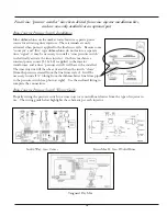
4.8 rinse Injector connections
Identify the point at which rinse additive will be injected into
the final rinse line,
refer to Figure 4-3.
NOTE: The injection point has to be installed a minimum
of 6" (15.2 cm.) below the vacuum breaker with the cabinet
mounted at or below that point. In many International
accounts the minimum distance beneath the vacuum
breaker is 30 cm. (11.8"). Install fitting using Teflon tape
or pipe sealant to prevent leakage.
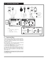
4.9 Hydraulic connections and Visual flow
Indicator
1. Connect 1/8" product discharge tubing between the outlet
of the pump squeeze tube and visual flow indicator,
refer
to Figure 4-3.
Note: The visual flow indicator is required for NSF
listing.
2.
Assemble the Visual Flow Indicator by inserting the 1/8"
tube fully into one of the two 1" sections of 1/4" OD x
1/8" ID PVC tubing provided.
3. Insert this injection tubing assembly fully into the outlet
end of the Flow Indicator tube, also called the sight
tube.
4. Secure all connections with the clamps provided.
5. Complete the outlet of the Visual Flow Indicator in the
same manner and extend the 1/8 tubing to the check
valve and injection fitting.
Refer to Figure 4-3.
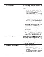
IMPORTANT: When the product is being injected into
the final rinse line, movement of the product will be
visible in the flow indicator tube. The dishmachine
operator must be instructed to observe the Flow
Indicator periodically to insure that product is in
fact being dispensed.
6. Trim and connect the 1/8" product pick-up tubing supplied
with the rinse injector to the inlet side of the pump
.
7. Connect 1/4" O.D. copper tubing from the water source to
the inlet side of the solenoid valve located at the bottom
on the GeoCenter cabinet,
refer to Figure 4-4.
8. Connect 1/4" O.D. copper tubing from the outlet side of the
solenoid valve to the Geosystem Detergent Dispenser.
Refer to the Installation and Operation Manual
of the
Geosystem Detergent Dispenser used to determine
wATER IN
SOLENOID
VALVE
TO GEOSYSTEM
DETERGENT
DISPENSER
VACuuM
BReAKeR
INJECTION
FITTING
CHeCK
VALVE
PRESSuRE
SWITCH
TO
GEOSYSTEM
RINSE
DISPENSER
Figure 4-4


