36
EN
420010268002
Blu 700.1 P Low Nox
TC = SHORT HEAD TL = LONG HEAD
Blu 700.1 P
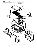
N° DESCRIPTION
code
1
AIR PRESSURE SWITCH
DUNGS LGW10 A2P
65323047
2
AIR INTAKE SET
65322346
3
PLUG WIELAND
6 pin
65322072
4
BURNER COVER
65324052
5
GLASS
65320487
6
PEED WINDOM FRAME
65320488
7
MOTOR
1100 W
65325323
8
FAN
250 x 84
65321777
9
AIR CONVEYOR
65320639
10 FAN SCOOP
65320622
11 AIR INTAKE
65324054
12 CONTROL BOX BASE
LANDIS
65320092
13 CONTROL BOX
LME21.330A2
65324220
14 IGNITION TRANSFORMER
65323227
15 REMOTE CONTROL SWITCH
MC9.10
65323126
16 MOTOR THERMAL RELAY
Lovato RF9 3-5A
65074495
17 MAIN SWITCH
cod.40100I1509
65323064
18 HIGH-LOW FLAME SWITCH
cod.03600I014
65323065
19 LAMP
EL/N-SC4 Elettrospring
65322053
20 FUSE SUPPORT
FUSIT FH-B528
65322181
21 IONIZATION CABLE
TC
65320948
TL
65322002
22 IGNITION CABLE
TC
65320940
TL
65320942
23 IONIZATION PROBE
65320902
24 IGNITION ELECTRODES
65320903
25 PRESSURE GAUGE
65321341
26 HEAD SUPPORT PIPE
65321649
27 HEAD PIPE
TC
65324339
TL
65324340
28 FIRING HEAD
65321646
29 HEAD CAP
65321647
30 DIFFUSER
65321653
31 TOOTH
(G20)
65324161
32 FRONT DISC
65320822
33 ROD
TC
65324341
TL
65324342
34 INNER ASSEMBLY
TC
65324351
TL
65324443
35 BLAST TUBE
TC
65324343
TL
65324344
36 GASKET ISOMART
65321115
37 ANTIJAMMING FILTER
65323170
38 PROTECTION
65324049
39 SHEET CLOSING
65324050