background image

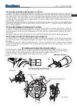
REGULACIÓN DE LA POTENCIA MÁXIMA DEL QUEMADOR

Posicionar el conmutador colocado sobre el cuadro de mandos a la posición de potencia max.y proceder como sigue: 

Regulación del caudal máximo del gas: 

obrar como indicado para regulación electroválvulas de gas, hasta conseguir el

caudal máximo del gas, determinado por una análisis de la combustión. Obrar sobre la varilla de regulación con una
llave hexagonal apropiada, y modificar la posición de la hoja de guía del excéntrico(3). Atornillando se aumenta el cau-
dal; destornillando se disminuye.

Regulación del caudal máximo del aire:

Corregir si hace falta esta posición  tocando los tornillos “1” después de haber

ajustado la tuerca  “2”. Fijar nuevamente el tornillo“2”.

REGULACIÓN DE LA POTENCIA MÍNIMA DEL QUEMADOR 

Posicionar el conmutador colocado sobre el cuadro de mandos a la posición de potencia mín.y proceder como sigue: 

Regulación del caudal mínimo del gas:

obrar sobre la varilla de regulación con una llave hexagonal apropiada, y modi-

ficar la posición de la hoja de guía del excéntrico. Atornillando se aumenta el caudal; destornillando se disminuye.

Regulación del caudal mínimo del aire:

modificar la leva de regulación de la posición de potencia mín. 

REGULACIÓN DE LAS POTENCIAS INTERMEDIAS DEL QUEMADOR

Obrar el servomotor con el conmutador (abertura o cierre) y ponerlo en posición 0 para bloquear la carrera. Para la
regulación proceder como sigue: 

Regulación de los caudales intermedios del gas:

obrar sobre la varilla de regulación

con una llave hexagonal apropiada, y modificar la posición de la hoja de guía del excéntrico(3). Atornillando se aumen-
ta el caudal; destornillando se disminuye.

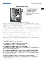
REGULACION CABEZA DE COMBUSTION 

La regulación de la posición de la cabeza de combustión es efectuada para obtener el mejor rendimiento de la combu-
stión. En caso de instalaciones con caudales mínimos, la cabeza es arredrada, con caudales máximos es adelantada. 

Ejecución

: - aflojar el tornillo A de fijación.  

- por medio de un destornillador rodar el tornillo B hasta conseguir la posición que se necesita. 
- atornillar el tornillo A.

– 

+

B

A

+

--

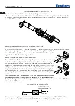
DESMONTAJE DEL TUBO DE LLAMA

POSICIÓN DE LOS ELECTRODOS

A

A

A A

SE

E

ZION

5

11,5

B

B

SEZIONE B-

-

B

7

,5

9

3

Electrodo de encendido

Sonda de ionización

ES

420010329600 

BLU 1500.1 PR

23

Summary of Contents for BLU 1500.1 PR

Page 1: ...20010329600 02 09 2010 BRUCIATORI A GAS PROGRESSIVI PROGRESSIVE GAS BURNERS BRULEURS GAZ PROGRESSIVES QUEMADOR DE GAS PROGRESIVOS IT EN FR ES RU BLU 1500 1 PR G N 30 700 mbar Low NOx L P G 45 500 mbar...

Page 2: ...motore N 2800 Combustibile P c i metano 35 9 MJ Nm3 8 570 kcal Nm3 P c i GPL 22 260 kcal Nm3 DIMENSIONI DI INGOMBRO MODELLO A B C D D1 E F G H I L M N O BLU 1500 1 PR 710 385 325 340 540 680 215 398 2...

Page 3: ...sta sul bruciatore Si avvia il motore ed inizia la preventilazione Il motoriduttore porta la serranda dell aria alla massima apertura in circa 30 secondi Quando il motoriduttore comple tamente aperto...

Page 4: ...urezza Descrizione 56 7 6 86 6 6 96 Togliere il coperchio per accedere alle camme di regolazione Lo spostamento delle camme va effettuato con l ausilio dell apposita chiavetta in dotazione Descrizione...

Page 5: ...minuisce Regolazione della portata minima dell aria agire sulla camma di regolazione posizione di apertura in fiamma potenza min REGOLAZIONE DELLE POTENZE INTERMEDIE DEL BRUCIATORE Con il commutatore...

Page 6: ...blocco del bruciatore Rimuovere l ostru zione dal condotto rimontare il coprechio C e ripristinare il funzionamento del bruciatore agendo sul pulsante di riar mo del blocco dell apparecchiatura NB La...

Page 7: ...nterruttore i termostati il motore pressione gas IL BRUCIATORE EFFETTUA LA PREVENTILAZIONE E AL TERMINE DEL CICLO VA IN BLOCCO Controllare la pressione dell aria e la ventola Controllare il pressostat...

Page 8: ...Motor kW 3 Rpm N 2800 Fuel L C V Natural gas 35 9 MJ Nm3 8 570 kcal Nm3 L C V LPG 22 260 kcal Nm3 12 400 600 800 1000 1200 1400 1600 1800 2000 600 800 1000 1200 1400 1600 1800 2000 2200 kW kcal h x 10...

Page 9: ...in the pipe tap on the burner Start the motor and begin preventilation The motor reducer brings the air damper into the fully open position within about 30 seconds When the motor NdT air damper is ful...

Page 10: ...ulate the burner s output through the following formula CALCULATION OF WORKING OUTPUT OF THE BURNER e x f kW s e Litres of gas s Time in seconds G20 34 02 G25 29 25 G30 116 G31 88 f Remove cover to ga...

Page 11: ...reduced if you unscrew it the flow rate increases Adjusting the minimum air flow rate adjust on limit switch for air damper Low Flame position adjustment ADJUSTING THE INTERMEDIATE BURNER CAPACITIES U...

Page 12: ...screw on the cover C and start the burner by pressing the control box rearm button Note The pressure measured at pressure port E must be within the limits of the pressure switch working range If not l...

Page 13: ...ower in the circit and the burner is connected that the gas pressure is right and the gas shut off cock is open that the control systems are properly connected If all these conditions have been satisf...

Page 14: ...230 400 Moteur kW 3 Tours par minute N 2800 Combustible L C V Natural gas 35 9 MJ Nm3 8 570 kcal Nm3 L C V gaz propane 22 260 kcal Nm3 12 400 600 800 1000 1200 1400 1600 1800 2000 600 800 1000 1200 1...

Page 15: ...On d marre le moteur et il com mence la preventilation Le motor ducteur porte le volet de l air l ouverture maximale dans 30 secondes Lors que le motor ducteur est compl tement ouvert un signal trans...

Page 16: ...DIS STAEFA LGB 22 Le coffret de s curit Landis d marre la turbine et commence le pre balayage de la chambre de combustion Le presso stat air contr le que le fonctionnement sera correct A la fin du pre...

Page 17: ...glage le came de r gulation de la position d ouverture en puissance min REGLAGE DES PUISSANCES INTERMEDIAIRES DU BRULEUR A l aide du commutateur d marrer le servomoteur et l arr ter sur une position...

Page 18: ...on du conduit visser le couvercle C et d marrer le br leur en appuyant sur la touche de r arme ment du coffret de s curit Note La pression mesur e la prise de pression E doit tre comprise dans les lim...

Page 19: ...r LE BRULEUR NE DEMARRE PAS Contr ler l interrupteur les thermostats le moteur la pression du gaz LE BRULEUR EFFECTUE LE PREBALAYAGE ET SE BLOQUE A LA FIN DU CYCLE Contr ler la pression de l air et le...

Page 20: ...0 1800 2000 600 800 1000 1200 1400 1600 1800 2000 2200 kW kcal h x 1000 mbar 200 400 200 0 2 4 6 8 10 Blu 1500 1 MODELO BLU 1500 1 PR Potencia t rmica m x kW 1550 kcal h 1 336 200 Potencia t rmica m n...

Page 21: ...ectuado con un manometro de gas conectado a la apropiada toma de presi n del quemador El motor arranque y empieza el prebarrido El motorreductor abre el cierre del aire a la abertura m xima en cerca d...

Page 22: ...evas tiene que ser efectuada con su apropiada llave de suministro Descripci n I Leva de regulaci n abertura del cierre del aire en potencia m x II Leva de regulaci n de la posici n del cierre al apaga...

Page 23: ...exc ntrico Atornillando se aumenta el caudal destornillando se disminuye Regulaci n del caudal m nimo del aire modificar la leva de regulaci n de la posici n de potencia m n REGULACI N DE LAS POTENCIA...

Page 24: ...nillar la tapa luego arrancar el quemador presionando el bot n de rearme del equipo de control Nota La presi n medida a la toma del aire E debe estar dentro de los limites del campo de trabajo del pre...

Page 25: ...hay corriente en la instalaci n y que el quemador sea conectado Que la presi n del gas sea la correcta y la v lvula de cierre est abierta Que los equipos de control est n debidamente conectados Cuando...

Page 26: ...240 M14 125 190 Optional D D1 12 400 600 800 1000 1200 1400 1600 1800 2000 600 800 1000 1200 1400 1600 1800 2000 2200 kW kcal h x 1000 mbar 200 400 200 0 2 4 6 8 10 Blu 1500 1 BLU 1500 1 PR K 1550 1...

Page 27: ...400 50 230 50 230 50 30 66 PR MD 3 2 2 30 30 100 CO2 9 7 G20 9 6 G25 11 7 I3B 11 7 I3P CO 75 ppm RU 420010329600 BLU 1500 1 PR 27 GPL CO2 11 7 CO 50 ppm CO2 9 6 CO 50 ppm...

Page 28: ...ec e sec 34 02 116 88 f 2 SELECTOR 0 AUTO 0 operating elements locked in an intermediate position operation on maximum capacity operation on minimum capacity AUTO automatic operation 1 3 LANDIS STAEFA...

Page 29: ...3 2 1 2 3 0 3 RU 420010329600 BLU 1500 1 PR 29 B A A A A A SE E ZION 5 11 5 B B SEZIONE B B 7 5 9 3 B B A A...

Page 30: ...MG22 min 2 A 0 50 0 100 A 3 A A B I L M N 60 20 12 30 37 18 M I L A B C D 1 1 2 0 5 0 8 E 0 1 10 N B F F 2 5 5 10 15 50 25 3 5 30 40 45 20 0 4 0 6 0 9 3 0 1 5 2 1 1 8 2 4 2 7 1 2 I L M N A B C D E F G...

Page 31: ...onamento alla massima poten 2 funzionamento alla minima potenza 3 funzionamento automatico B lampada di funzionamento C lampada di blocco termico D fusibile E interruttore I O F pulsante di sblocco A...

Page 32: ...T7 T8 YVGS YVG DUNGS VPS 504 S3 BEM06163 2 BLU 1500 1 1700 1 R 1700 1 2000 1 PR LANDIS SQN31 251A2700 LANDIS LGB22 330A27 DUNGS VPS 504 ER 27 03 2006 SWITCH MANUAL AUTOMATIC INTERRRUPTEUR MANUEL AUTOM...

Page 33: ...ILADOR RELAIS THERMIQUE MOTEUR VENTILATEUR MOTOR THERMAL RELAY FAN MOTOR TELERRUPTOR MOTOR VENTILATOR CONTACTEUR MOTEUR VENTILATEUR REMOTE CONTROL SWITCH FAN MOTOR CONTATTORE MOTORE VENTILATORE LAMPAD...

Page 34: ...4 5 6 7 8 9 11 12 13 14 15 16 36 37 40 25 3 38 10 2 0 AUTO 0 I 18 19 19 20 17 22 21 34 35 29 24 23 28 30 27 26 33 32 31 39 0 AUTO 0 I K6 RWF 40 PGM PGM EXIT EXIT 43 KIT MD 34 420010329600 BLU 1500 1 P...

Page 35: ...9 LAMPADA LAMP EL N SC4 Elettrospring 65322053 20 PORTA FUSIBILE FUSE SUPPORT FUSIT FH B528 65322181 21 CAVO RIVELAZIONE IONIZATION CABLE TC TL 65322003 22 CAVO ACCENSIONE IGNITION CABLE TC TL 6532094...

Page 36: ...ng 65322053 20 PORTEFUSIBLE PORTAFUSIBLE FUSIT FH B528 65322181 21 CABLE D IONISATION CABLE DE CONTROL LLAMA TC TL 65322003 22 CABLE D ALLUMAGE CABLE DE ENCENDIDO TC TL 65320946 23 SONDE D IONISATION...

Page 37: ...RF25 6 10 A 65323108 17 cod 40100I1509 65323064 18 65323067 19 EL N SC4 Elettrospring 65322053 20 FUSIT FH B528 65322181 21 TC TL 65322003 22 TC TL 65320946 23 65320902 24 65324442 25 65321230 26 6532...

Page 38: ...RU ES FR EN IT 420010329600 BLU 1500 1 PR 38...

Page 39: ...39 420010329600 BLU 1500 1 PR IT EN FR ES RU...

Page 40: ...ili senza pregiudicarne le caratteristiche principali ECOFLAM BRUCIATORI S p A reserves the right to make any adjustments without prior notice which it considers necessary or useful to its products wi...

Reviews: