


ETS 73
0548-990-51---60g_2019.10.indd
B
A
C
D
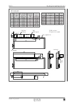
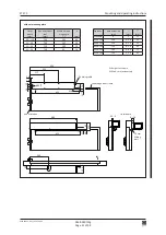
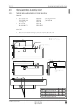
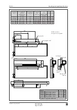
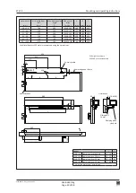
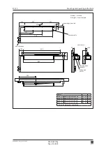
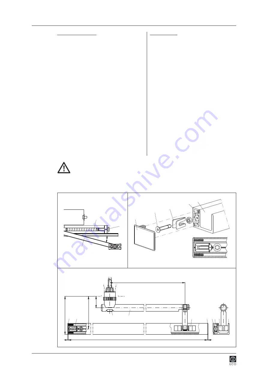
400
620
1,5
1,5
27
76,5 / 52,5
89,5 / 65,5
E F
C
G
D
F
E
G
F
D
15°
B
H
I
1,5 Nm
!
0548-990/52g
Page 38 of 98
Mounting and operating instructions
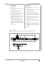
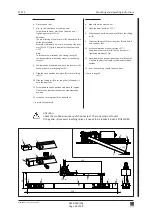
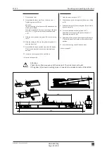
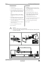
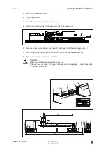
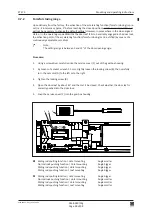
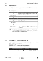
Attention:
Check the motional sequence of the door leaf:
The rods must not touch. If the glider (C) makes screeching noises, it needs to be lubri
-
cated with a little WD40.
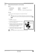
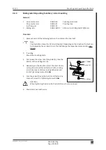
Drive mechanism standard
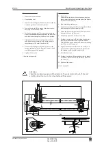
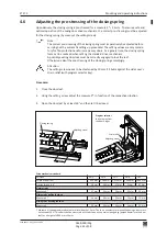
2. Close the door leaf
.
3. Install the mounting profile (E) on the door leaf.
4. Prior to the installation of the drive mechanism: screw
down the rotating arm (B) on the drive mechanism
(with a 15° offset = 1 grid increment of the output
shaft).
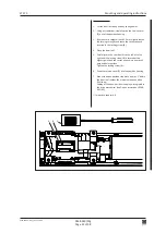
Note:
To facilitate the installation, the closing spring (H)
can be completely released by means of the setting
screw (I).
5. While mounting the drive mechanism, push the rota
-
ting arm (B) back by the pre-stressing angle of 15°.
6. Push the guide profile (G) over the glider (C) and hook
it into the mounting profile (E).
7. On both sides insert and screw down the expansion
element (F) with 1,5 Nm.
8. Snap in the covering caps (D) on both sides.
forward to chapter 4.6
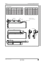
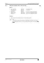
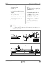
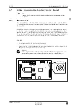
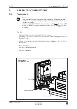
Inverse application
2. If existing:
Sub-assemble the drive-internal open position stop
piece, integrated in the drive mechanism (see Option
instructions 0548-992/02).
3. Mount the drive mechanism.
4. Install the mounting profile (E) on the door leaf.
5. Hook the guide profile (G) into the mounting pro
-
file (E), on both sides insert and screw down the
expansion element (F) with 1,5 Nm.
6. Completely open the door leaf (max. 115°).
7. Insert glider (C) into guide profile (G) and screw down
the rotating arm (B) on the drive mechanism.
8. Snap in the covering caps (D) on both sides.
back to page 25