background image

 22 


                     7058-206E  


          August 30, 2016

HEATILATOR ECO CHOICE

B.  Exhaust Blower Replacement

1.  Turn down the thermostat, let appliance completely cool 

and then unplug appliance before servicing.

2.  Remove both upper and lower right side curtains.  

Figure 

22.2. on page 22. 

3.  Disconnect 2 white wires from the white and blue wires of 

the exhaust blower.

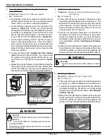
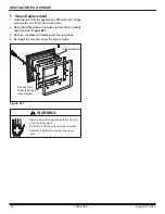
4.  There  is  a  removable  plate  on  the  exhaust  blower.  

Depending on the model, use a 1/4 inch socket, or 1/4 

inch Nut Driver or #2 Phillips Head screw driver to loosen 

the 6 screws in the keyhole shaped holes and rotate the 

plate.  It is only necessary to loosen screws. 

Figure 22.1.

5.  Remove the exhaust blower and gasket.
6.  Check for degradation on the gasket and replace if nec-

essary using the gasket included in the kit.

7.  Re-install in reverse order.

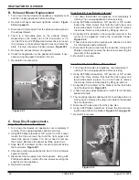
Figure 22.1

Exhaust Blower

C.  Snap Disc Replacements

Snap Disc #1 - Convection Blower

1. Turn down thermostat, let appliance cool completely if 

running. Then unplug appliance before servicing. 

2. Using #2 Phillips screwdriver, 3/8” wrench, or 3/8” socket 

loosen the three screws that hold the right upper and 

lower side panels in place. You do not need to remove 

the screws. Remove side panels by lifting up and out.

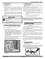
3. Snap disc #1 is located on the convection plenum below 

the feed motor. 

Figure 22.1

.

4. It has two purple wires attached to it with 1/4 inch female 

spade terminals.

5. Disconnect the two wires from the snap disc.  Using a #2 

Phillips screwdriver, remove the two screws securing the 

snap disc to the appliance. 

6. Re-install in reverse.

Snap Disc #2 - Fuel Delivery Interrupt

1. Turn down thermostat, let appliance cool completely if 

running. Then unplug appliance before servicing. 

2. Using #2 Phillips screwdriver, 3/8” wrench, or 3/8” socket 

loosen the three screws that hold the right upper and 

lower side panels in place. You do not need to remove 

the screws. Remove side panels by lifting up and out.

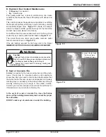
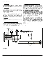
3. Snap disc #2 is located on the convection plenum in the 

center  of  the  appliance  above  the  convection  blower. 

Figure 22.2

.

4. It has a black wire and an orange wire attached to it with 

1/4 inch female spade terminals.

5. Disconnect the two wires from the snap disc. Using a #2 

Phillips screwdriver, remove the two screws securing the 

snap disc to the appliance. 

6. Re-install in reverse.

Snap Disc #3 - Feed Motor - Manual Reset

1. Turn down thermostat, let appliance cool completely if 

running. Then unplug appliance before servicing. 

2. Using #2 Phillips screwdriver, 3/8” wrench, or 3/8” socket 

loosen the three screws that hold the right upper and 

lower side panels in place. You do not need to remove 

the screws. Remove side panels by lifting up and out.

3. Snap disc #3 is located on the bracket on the feed tube 

near the feed motor. 

Figure 22.1

.

4. It has a two gray wires attached to it with 1/4 inch female 

spade terminals.

5. The locating bracket is attached to the feed tube with an 8 

X 32 wing nut. Remove the wing nut to detach the bracket 

from the feed tube.

5. Disconnect the two wires from the snap disc. 
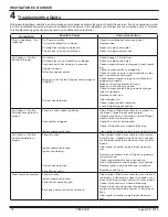
6. Using a #2 Philips screwdriver, remove the screw secur-

ing the snap disc to the bracket. 

Figure 23.1 on page 23

.

7. Re-install in reverse.

Figure 22.2

Snap Disc #1

Snap Disc #3

Snap Disc #2

Summary of Contents for ECO-ADV-PS35

Page 1: ...operty damage personal injury or death Do not store or use gasoline or other flam mable vapors and liquids in the vicinity of this or any other appliance Do not overfire If heater or chimney con nector glows you are overfiring Overfiring will void your warranty Comply with all minimum clearances to combustibles as specified Failure to comply may cause house fire WARNING CAUTION Tested and approved...

Page 2: ...émas l indiquent Mesurez la distance du devant I de la surface de la porte vitrée 2015 2016 2017 JAN FEB MAR APR MAY JUN JUL AUG SEP OCT NOV DEC 34 400 34 400 4001508 ECO ADV PS35 Conforms to ASTM STD E1509 Certified to ULC STD S627 ULC ORD C1482 M1990 Room Heating Pellet Burning Type UM 84 HUD FOR USE ONLY WITH PELLETIZED WOOD FUEL Do not use any other type of fuel B Sample of Serial Number Safet...

Page 3: ... F Before Your First Fire 8 G Hopper Lid Latch and Hopper Switch 9 H Starting Your First Fire 9 I Fire Characteristics 10 J Feed Rate Adjustment Instructions 10 K Ignition Cycles 10 L Clear Space 10 M Quick Start Guide 11 N Frequently Asked Questions 12 3 Maintenance and Service 13 A Proper Shutdown Procedure 13 B Quick Reference Maintenance Chart 13 C General Maintenance 13 D High Ash Fuel Conten...

Page 4: ...be free from defects in materials and workmanship at the time of manufacture After installation if cov ered components manufactured by HHT are found to be defective in materials or workmanship during the applicable warranty period HHT will at its option repair or replace the covered components HHT at its own discretion may fully discharge all of its obligations under such warranties by replacing t...

Page 5: ...tightly sealed constructions insufficient make up air supply or handling devices such as exhaust fans or forced air furnaces or other such causes 6 use of fuels other than those specified in the operating instructions 7 installation or use of components not supplied with the appliance or any other components not expressly authorized and approved by HHT 8 modification of the appliance not expressly...

Page 6: ...th 5mm ceramic glass Please contact your dealer for replacement glass D Electrical Rating on high Model PS35 115 VAC 60 Hz Start 3 8 Amps Run 1 3 Amps Model PS50 115 VAC 60 Hz Start 5 1 Amps Run 3 0 Amps Model CAB50 115 VAC 60 Hz Start 5 1 Amps Run 3 0 Amps E Mobile Home Approved This appliance is approved for mobile home installa tions when not installed in a sleeping room and when an outside com...

Page 7: ...sh content Higher Ash Content Material Hardwoods with a high mineral content Fuel that contains bark Standard grade pellets high ash pellets Lower Ash Content Material Softwoods Fuels with low mineral content Premium grade pellets Clinkers Minerals and other non combustible materials such as sand will turn into a hard glass like substance called a clinker when heated in the firepot Trees from diff...

Page 8: ...will go off and the appliance will shut down 2 Heat Output Controls This appliance is equipped with a heat output control switch that has three settings or burn rates low medium and high Figure 8 1 The appliance will turn on and off as the thermostat demands When the thermostat calls for heat the appliance will start up at the burn rate for which it is set If the appliance is set at one of the low...

Page 9: ...trol switch mounted on the back of the appliance in the upper left corner Figure 8 1 on page 8 Turn it to the high setting by pushing the top of the control switch in and then adjust the thermostat to its highest setting 4 Look through the hole in the left lower side panel and you will see the red call light on the control box will be on Figure 9 3 This indicates the thermostat is calling for heat...

Page 10: ...ely 10 minutes This blower transfers heat from your appliance into the room and will continue to run after the thermostat has stopped calling for heat until the appliance has cooled down 3 Occasionally the appliance may run out of fuel and shut itself down When this happens the red call light will be on See Figure 9 3 page 9 To restart it fill the hopper and press the reset button When you press t...

Page 11: ...cord into the wall receptacle Turn the thermostat on Turn the thermostat to off If the feed tube is empty or this is the first fire add a handful of pellets to the firepot Do not add extra fuel to the firepot if the feed tube has already been primed Overfilling the fire pot will cause smoky start ups If the fire dies out after a few minutes of operation it will be nec essary to push the reset butt...

Page 12: ... lubricate the blowers to quiet them down The most often cause of noisy blowers is from the impellers becoming dirty over time See General Maintenance Cleaning under Maintaining Servicing Appliance in the owner s manual No form of lubrication should ever need applied to the blowers Why are different components cycling on and off in my appliance at random The selector switch on control box may be o...

Page 13: ...ng on the fuel type OR X Blower Convection Every 25 bags or more fre quently depending on operat ing environment OR X Door Handle Gasket Inspection Prior to heating season OR X Exhaust Path Drop Tube and Behind Baffles Every 25 bags or more fre quently depending on ash build up OR X Firepot Cleaning Rod Every 1 bag of fuel OR X Firepot with Clean out Tool Every 5 bags of fuel OR X Firebox Prepare ...

Page 14: ...is loose If the rod is hard to pull it may be necessary to use your firepot clean out tool to chip away material that has built up on the bottom plate of the firepot and to push out any clinkers while in the open position d To close the firepot floor slightly raise the cleaning rod and then push it back into place If you have closed the cleaning rod properly pushed all the way in you will not see ...

Page 15: ...hopper to prevent sawdust build up A combination of sawdust and pellets on the bottom end of the auger reduces the amount of fuel supply to the firepot This can result in nuisance shutdowns and mis starts a The appliance must be in complete shutdown Allow the appliance to completely run out of pellets and cool down b Empty the hopper of any remaining pellets c Vacuum the hopper and feed tube NOTE ...

Page 16: ...direct access to the exhaust blower d Vacuum the blower s impellers Use care not to bend or damage the blower fins NOTE Hearth Home Technologies recommends to use a heavy duty vacuum cleaners specifically designed for solid fuel appliance cleaning 12 Cleaning Convection Blower Requires No Lubrication Frequency Yearly or more frequently depending on Dust Dirt build up By Homeowner or Qualified Serv...

Page 17: ... or lack of maintenance can cause the firepot to overfill Follow proper shutdown procedure if ash buildup exceeds halfway point in firepot Failure to do could result in smoking sooting and possible hopper fires Figure 17 3 Figure 17 1 Figure 17 2 Correct Flame Height Yellow White in Color Incorrect Flame Height Tall Lazy Flame Orange in Color Pellets Back up in Feed Tube Ash build up in Firebox Fi...

Page 18: ...age Replace control box Close Hopper Lid Check hopper switch operation Check adjust magnet position Call light on No fire Partially burned fuel in firepot Firepot is dirty missed ignition Vent system plugged Igniter chamber blocked Clean firepot Make sure there is no clinker in the firepot Close firepot bottom plate Clinkers may have to be broken up with firepot clean out tool or other means Check...

Page 19: ...lowing into the venting system can pressurize the firebox causing loss of vacuum Replace vacuum switch Empty hopper of fuel Use a wet dry vacuum cleaner to remove remaining fuel from hopper including feed tube Check feed chute for obstructions Remove feed assembly check for obstruction Check that set screw is tight on feed spring shaft at end of feed motor Check connections on feed motor replace i...

Page 20: ...venting system Clean exhaust path Try a different brand of pellets Reduce feed rate using feed rate adjustment control rod located inside hopper See owner s manual for correct setting for your model and how to adjust control box setting Nuisance shutdowns Low flame Sawdust buildup in hopper Feed motor is reversing Feed motor is weak Feed bearing adjustment Defective thermocouple Defective control ...

Page 21: ...nylon wire retainer if applicable Model ECO ADV PS35 has 2 black wires and Model ECO ADV PS50 and ECO CAB50 has 1 black and 1 white wire coming from the blower 7 Remove the wing bolt and move the blower and hold down bracket toward the back of the appliance to release the locating tab Figure 21 3 Pull the blower out from under the convection plenum Slide the blower out of the appliance Disconnect ...

Page 22: ...to the appliance 6 Re install in reverse Snap Disc 2 Fuel Delivery Interrupt 1 Turn down thermostat let appliance cool completely if running Then unplug appliance before servicing 2 Using 2 Phillips screwdriver 3 8 wrench or 3 8 socket loosen the three screws that hold the right upper and lower side panels in place You do not need to remove the screws Remove side panels by lifting up and out 3 Sna...

Page 23: ...irepot cleaning rod etc 5 Re install the ash drawer and side panel and re connect the power E Baffle Removal Replace 1 Shut down the appliance by turning down the thermostat and let the appliance completely cool down 2 Remove the center baffle first by using the handle at the top of the baffle and pull up and then towards you The hooks on the baffle will slide out of the slots in the bracket Figur...

Page 24: ...ury WARNING F Glass Replacement 1 Open the door from the appliance by lifting door off of hinge pins and lay on a flat surface face down 2 Using a Phillips Head screw driver remove the 4 brackets and set aside Figure 24 1 3 Remove old glass and replace with the new glass 4 Re install the brackets using the same screws Glass Assembly 1 2 3 4 Remove the 4 brackets outlined in the diagram Figure 24 1...

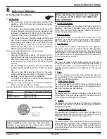
Page 25: ...ring harness are replaced as one component 11 Power Supply The power outlet is located behind the control box on the back of the appliance lower left corner Check the wall receptacle for 120 volt 60 Hz standard current Make sure the outlet is grounded and has the correct polarity A good surge protector is recommended When describing the location of a component it is always AS YOU FACE THE FRONT OF...

Page 26: ...is an orange and a black wire connected to it This snap disc will turn off the feed system which will turn off the appliance if an over fire condition should occur or if the convection blower should fail to operate If this occurs you will have to manually reset the snap disc 18 Snap Disc 3 Back Burn Protector 250 F Snap disc 3 is mounted on the back of the auger tube in the center of the appliance...

Page 27: ...x Junction Box Red Call Light Fuse Convection Blower LOCATED BEHIND LEFT SIDE PANELS Feed Motor Vacuum Switch Combustion Blower LOCATED BEHIND RIGHT SIDE PANELS Back of Appliance Power Outlet Terminal Block Center 2 Screws for Thermostat Wires Heat Output Switch Reset Button B Component Locations ...

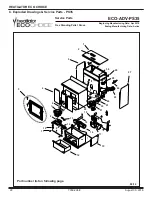
Page 28: ...inning Manufacturing Date Apr 2010 Ending Manufacturing Date Active ECO ADV PS35 Part number list on following page Free Standing Pellet Stove 1 2 4 5 6 7 3 8 9 10 14 15 16 12 13 11 17 18 19 20 21 23 25 24 26 29 30 28 27 22 08 16 C Exploded Drawings Service Parts PS35 ...

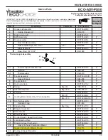
Page 29: ...1680 Y 6 1 Thermocouple Protection Tube SRV7034 186 Y 6 2 Half Clip 7000 321 6 3 Thermocouple 812 4470 Y 7 Firepot Assembly SRV7034 072B Y Gasket Firepot 7034 190 Y 8 Firepot Bottom 7034 153 Y 9 Rail Auto Clean SRV7034 152 Y 10 Spring Pkg of 4 7000 513 4 Y 11 Hitch Pin Clip 3 32 Pkg of 10 7000 374 10 Y 12 Pull Rod SRV7058 141 13 Heating Element Assembly 18 Loop Igniter Pkg of 1 SRV7000 462 Y Pkg o...

Page 30: ...ual Reset Left 230 1960 Y 25 Feed Assembly SRV7058 007 Y Feed Bearing SRV7000 598 Y Feed Motor 812 4421 Y Feed Spring Assembly Only SRV7001 046 Y 26 Snap Disc SRV230 1290 Y 27 Side Curtain Right SRV7058 124 28 Vacuum Switch SRV7000 531 Y 29 Hopper Switch SRV7000 612 Y 30 Bumper Rubber Pkg of 12 SRV224 0340 12 Y Fuse 7 Amp Junction Box Pkg of 10 812 0380 10 Y Component Pack SRV7058 019 Cleanout Too...

Page 31: ...44 Outside Air Collar Assembly 7001 045 Trim Plate Outside Air Kit 412 7100 Smart Batt Il 841 0970 Smart Stat Il 841 0960 Thermostat Mechanical 812 3760 Y Thermostat Programmable 811 0520 Top Vent Adapter TPVNT 5 Component Pack SRV7058 054 Vent Adapter 3 4 811 0720 Vent Adapter 90 Cleanout 811 0610 Fastener Packs Rivnut Repair Kit 1 4 20 3 8 16 Rivnut Tools RIVNUT REPAIR Y Bolt Hex Head Pkg of 10 ...

Page 32: ...inning Manufacturing Date Apr 2010 Ending Manufacturing Date Active ECO ADV PS50 Part number list on following page Free Standing Pellet Stove 1 2 4 5 6 7 3 8 9 10 14 15 16 12 13 11 17 18 19 20 21 23 25 24 26 29 30 28 27 22 08 16 D Exploded Drawings Service Parts PS50 ...

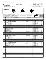
Page 33: ...80 Y 6 1 Thermocouple Protection Tube SRV7034 186 Y 6 2 Half Clip 7000 321 6 3 Thermocouple 812 4470 Y 7 Firepot Assembly SRV7034 072B Y Gasket Firepot 7034 190 Y 8 Firepot Bottom 7034 153 Y 9 Rail Auto Clean SRV7034 152 Y 10 Spring Pkg of 4 7000 513 4 Y 11 Hitch Pin Clip 3 32 Pkg of 10 7000 374 10 Y 12 Pull Rod SRV7058 141 13 Heating Element Assembly 18 Loop Igniter Pkg of 1 SRV7000 462 Y Pkg of ...

Page 34: ...ual Reset Left 230 1960 Y 25 Feed Assembly SRV7058 007 Y Feed Bearing SRV7000 598 Y Feed Motor 812 4421 Y Feed Spring Assembly Only SRV7001 046 Y 26 Snap Disc SRV230 1290 Y 27 Side Curtain Right SRV7059 124 28 Vacuum Switch SRV7000 531 Y 29 Hopper Switch SRV7000 612 Y 30 Bumper Rubber Pkg of 12 SRV224 0340 12 Y Fuse 7 Amp Junction Box Pkg of 10 812 0380 10 Y Component Pack SRV7058 019 Cleanout Too...

Page 35: ... 044 Outside Air Collar Assembly 7001 045 Trim Plate Outside Air Kit 412 7100 Smart Batt Il 841 0970 Smart Stat Il 841 0960 Thermostat Mechanical 812 3760 Y Thermostat Programmable 811 0520 Top Vent Adapter TPVNT 5 Vent Adapter 3 4 811 0720 Vent Adapter 90 Cleanout 811 0610 Fastener Packs Rivnut Repair Kit 1 4 20 3 8 16 Rivnut Tools RIVNUT REPAIR Y Bolt Hex Head Pkg of 10 25221A 10 Y Guide Pin Sle...

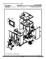
Page 36: ...inning Manufacturing Date May 2011 Ending Manufacturing Date Active Part number list on following page Pellet Cabinet Style Stove 1 2 3 4 5 6 7 8 9 10 11 12 13 14 15 16 17 18 19 21 20 25 24 23 22 26 27 28 29 30 08 16 E Exploded Drawings Service Parts CAB50 ...

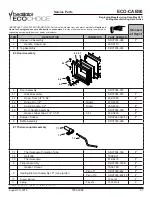
Page 37: ...ssembly SRV7058 014 4 1 Glass Assembly SRV7058 015 Y 4 2 Rope Door 3 4 X 84 832 1680 Y 4 3 Hinge Pin 1 2 Nickel 430 5320 4 4 Spring Handle 1 2 Nickel 250 8330 Y 4 5 Door Handle Assembly SRV7058 030 Y Gasket Glass Tape 3 4 X 1 8 5 Ft 832 0460 Y 5 Bumper Rubber SRV224 0340 12 Y 6 Baf e Assembly SRV7059 026 7 1 Thermocouple Protection Tube SRV7034 186 Y 7 2 Half Clip 7000 321 7 3 Thermocouple 812 447...

Page 38: ... Blower Round 812 4710 Y 19 Casting Exhaust Transition 180 0190 20 Convection Blower 220 CFM SRV7000 108 Y 21 Wire Harness SRV7058 150 Y 22 Blower Retainer SRV7058 148 23 Control Board 3 Speed Eco Choice SRV7058 188 Y 24 Snap Disc F110F 20 1 SRV230 1220 Y 25 Snap Disc L175F Manual Reset 2 230 1960 Y 26 Feed Assembly SRV7058 007 Y Feed Bearing SRV7000 598 Y Feed Motor 812 4421 Y Feed Spring Assembl...

Page 39: ...Outside Air Kit 412 7100 Outside Air Kit 3 OAK 3 Reset Button Assembly SRV7000 040 Smart Batt Il 841 0970 Smart Stat Il 841 0960 Thermostat Mechanical 812 3760 Y Thermostat Programmable 811 0520 Top Vent Adapter TPVNT 5 Touch Up Paint 812 0910 Vent Adapter 3 4 811 0720 Vent Adapter 90 Cleanout 811 0610 Baf e Center Back SRV7058 166 Fastener Packs Rivnut Repair Kit RIVNUT REPAIR Y Bolt Hex Head 1 4...

Page 40: ...olville WA 99114 Division of HNI INDUSTRIES Please contact your Heatilator dealer with any questions or concerns For the number of your nearest Heatilator dealer log onto www heatilator com This product may be covered by one or more of the following patents United States 5341794 5263471 6688302 7216645 7047962 or other U S and foreign patents pending We recommend that you record the following pert...

Reviews: