


6
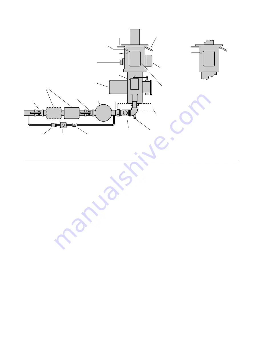
Figure 5 – Components Identification
5.0 Start-Up & Adjustment
Refer to the above illustration for component identification and location.
Initial Start-up Instructions
Close the manual main gas and pilot gas cocks.
Turn the burner on/off switch to “on.”
Open the manual main gas cock and then the pilot gas cock. Always open these two
valves in this sequence; reversing the sequence may blow out the pilot as the control
motor moves to the high fire position.
After the pilot gas cock is opened, the pilot should light, the automatic main gas valve
should open to establish a low fire flame, and the control motor should move the air
butterfly valve to the open—or high fire—position. Pilot gas flow is set at the Eclipse
factory during test firing and should be satisfactory for most applications. If pilot adjust-
ment is required, see the detailed instructions in Figure 7. Pilot gas flow should be the
minimum that will give reliable ignition and a steady flame signal.
Check Flue Gas
Drive the burner to high fire. Using a flue gas analyzer, measure the flue gas compo-
nents in the exit end of the immersion tube. Adjust the gas butterfly to produce 2 to
4% O
2
, or 10 to 10.5% CO
2
for natural gas.
Adjust High Fire Gas Flow
Using Tag Settings: Each burner is test fired at Eclipse before shipment and supplied
with a tag (Figure 6) showing the differential gas pressure that corresponds to maxi-
mum rated input. Attach a manometer as shown in Figure 6, and, if necessary, adjust
the air butterfly linkage until the gas differential pressure matches the pressure drop re-
corded on the tag. The differential pressure on the tag is for natural gas. For propane,
multiply this pressure by 0.4.
Using A Gas Metering Orifice: If a gas metering orifice was installed to provide more
accurate gas flow measurements, use a manometer to measure the pressure drop
across the orifice. If necessary, adjust the air butterfly linkage to produce the pressure
drop that corresponds to the desired high fire gas flow.
Ignition
Transformer
Flame Monitor
(Standard
Burner Only)
Wiring Box
IRI Only
Ignition Plug
#18193
Air Flow Switch
Control Motor
Blower Motor
Pilot
Solenoid
Pilot
Regulator
Pilot
Adjusting Cock
Peepsight
Union
Flame Rod Port,
1/2" N.P.T.
Use Rod
#16946-1**
U.V. Scanner,
124 IP*
U.V. Scanner,
132 IP*
U.V. Scanner,
140, 148 & 156 IP*
* All U.V. scanner ports are 1/2"
N.P.T. Install the scanner in these
ports when it is substituted for a
flame rod.
** Cut the electrode length to 4-1/2"
(114mm) for the 124 & 132 IP, and
5" (127mm) for the 140, 148 & 156 IP
Gas Adjusting
Valve
Manual
Main
Gas Cock
Automatic Gas
Shut-Off Valve(s)
Manual
Main
Gas Cock
Proportionator


