


4
4.0 Installation
(continued from page 2)
Leave Room For Adjustment
Immerso-Pak burners can be purchased with three different valve train packages. All
three packaging options integrate an adjustable bias proportionator. Thus, allow a
minimum of 6" (152 mm) of space beneath the proportionator stem for bias adjust-
ment, as shown in Figure 3.
Gas Metering Orifice
Each burner is test fired at Eclipse before shipment and supplied with a tag (Figure 6)
showing the differential gas pressure that corresponds to maximum rated input. This
provides only an approximate measurement of gas flow. For more precise measure-
ment, or if the burner will be operated at less than maximum input, install a gas meter-
ing orifice upstream of the burner.
When using a gas metering orifice, provide a straight run at least ten pipe diameters
upstream and at least five diameters downstream of the orifice. Failure to comply will
cause inaccurate meter readings.
Piping Suggestions
Strictly follow the system designer’s recommendations on pipe sizing and layout. If you
insert piping elbows not planned for in the original design, you may introduce exces-
sive pressure losses which can prevent the system from performing properly.
Use flexible nipples on burner air and gas inlets. Solid piping may restrain the burner
from thermal expansion and damage the burner or its piping components.
Do not use the burner assembly to support the piping.
Gas piping must comply with American National Standard “National Fuel Gas Code”
(NFPA No. 54 or ANSI Z223.1)*, or must be acceptable to the authority having jurisdic-
tion.
General Wiring Suggestions
See Figure 4 for wiring diagrams.
Electrical wiring must comply with the National Electric Code*, (NFPA Std. 70 or ANSI-
CI 1981), or must be acceptable to the authority having jurisdiction.
*Available from:
National Fire Protection Association
American National Standard Institute
Batterymarch Park
1430 Broadway
Quincy, MA 02269
New York, NY 10018
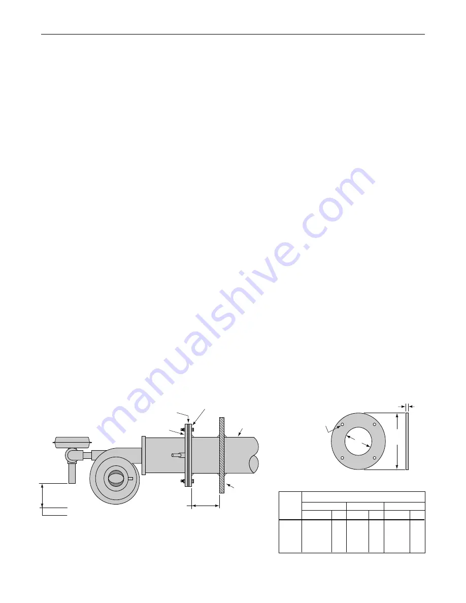
Figure 3 – Burner Mounting
Allow 6" (152 mm) Of Space
Beneath Proportionator Stem
For Bias Adjustment
Tank Wall
Immersion
Tube
Companion Flange
(By Customer)
Gasket
6"
(152 mm)
Maximum
Burner
Mounting Flange
Four
Mounting Holes
7/16" (11mm) Dia.
On “C” B.C.
1/4"
(6 mm)
“B”
Dia.
“A”
Dia.
Dimensions
A
B
C
Burner
Inches
mm Inches mm Inches mm
124
6-11/16 170 11-7/8 302 10-11/16 271
132
8-11/16 221 11-7/8 302 10-11/16 271
140
10-13/16 275 14-7/8 378
14
356
148
12-13/16 325 14-7/8 378
14
356
Companion Flange Dimensions


