background image

XDM® -100 

Physical Description 

417006-2005-013-A02 

ECI Telecom Ltd. Proprietary 

7-3 

FCU

I1

I5

I2

I6

I3

I7

I4

I8

MXC-A

A1

A2

MXC-B

B1

B2

ECU

B2


Figure 


7-2:  XDM-100 slot allocation 

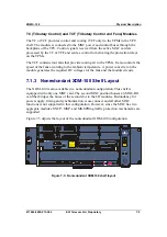
7.1.2  Expanded XDM-100 Shelf with I/O Protection 

A TPU shelf can be mounted on top of the XDM-100 basic shelf to add protection of 
electrical I/O modules.  

The TPU is a single-shelf cage with slots for the Tributary Protection Modules 
(TPMs) and Tributary Control (TC) or Tributary Control and Fans (TCF) modules. 
The modules are distributed as follows: 

♦ 

Four (4) slots flexibly allocated for TPMs (single-slot or double-slot modules 
are supported) 

♦ 

One (1) slot allocated for the TC or TCF module 

Each TPM is connected to the operating and protection modules of the XDM-100 
shelf respectively. If a failure is detected in one of the operating I/O modules, the 
XDM-100 control system sends control signals to the appropriate TPM relays to 
switch traffic from the operating I/O module to the protection module. Several types 
of TPM modules for 1:1 or 1:3 protection schemes are supported. 

The TC or TCF is connected to the DC and control buses of the MXC cards via the 
TPU backplane. It controls the switching of traffic from the main to protection I/O 
module by relays in the corresponding TPM. In addition, the TCF has four fans that 
provide cooling air to the modules installed in the TPU (optional). 

The TPU is a 231 mm deep, 443 mm wide, and 75 mm high unit. It connects to a 
connector on top of the XDM-100 shelf that provides the power and control buses 
required for its operation. When the TPU is not installed, a protection cap covers this 
connector. 

Summary of Contents for XDM-100

Page 1: ...XDM 100 Miniature MSPP for Metro Access and Cellular Networks General Description ...

Page 2: ...express or implied ECI Telecom s standard limited warranty stated in its sales contract or order confirmation form is the only warranty offered by ECI Telecom The documentation and or disk is provided AS IS and may contain flaws omissions or typesetting errors No warranty is granted nor liability assumed in relation thereto unless specifically undertaken in ECI Telecom s sales contract or order co...

Page 3: ...XDM 100 ...

Page 4: ...IMPORTANT XDM platforms are supplied in two versions for SDH and SONET The information contained in this document is applicable to both versions of the platforms ...

Page 5: ... 2 Multi ADM and Multi TM Modes 3 4 3 4 MXC Functionality 3 5 3 5 Data Services 3 6 3 5 1 Benefits and Features 3 6 3 6 XDM 100 Traffic I O Interface Modules 3 7 4 System Design 4 1 4 1 Control and Communication 4 2 4 1 1 Internal Control and Processing 4 2 4 1 2 Communication with External Equipment and Management 4 2 4 1 3 NE Software and Configuration Backup 4 3 4 1 4 Built in Test BIT 4 3 4 2 ...

Page 6: ...5 5 5 3 2 Multiplex Section Shared Protection Ring MS SPRing and Bidirectional Line Switched Ring BLSR 5 6 6 Management 6 1 6 1 Layered Architecture 6 1 6 2 Client Server Architecture 6 2 6 3 Integration with Other Products 6 2 6 4 eNM LightSoft Network Manager 6 2 6 4 1 Management Interfaces 6 3 6 4 2 User Interface 6 3 6 4 3 Topology Management 6 4 6 4 4 Trail Configuration 6 5 6 4 5 Fault Manag...

Page 7: ...5 7 2 Rack Installation 7 6 7 3 Main Cross Connect and Control MXC and External Connection Unit ECU Cards 7 7 7 3 1 MXC Cards 7 7 7 3 2 ECU Cards 7 8 7 4 I O and Aggregate Modules 7 9 7 4 1 I O Modules 7 9 7 4 2 Aggregate Modules 7 10 8 XDM 100H 8 1 8 1 Applications 8 1 8 2 Protection 8 2 8 2 1 Optical Protection 8 2 8 3 Physical Description 8 5 8 3 1 Tributary Protection Unit Optical CWDM Unit TP...

Page 8: ...Contents XDM 100 iv ECI Telecom Ltd Proprietary 417006 2005 013 A02 ...

Page 9: ...1 Path protection switching in a bidirectional self healing ring 5 2 Figure 5 2 Path diversity protection switching in a mixed equipment ring 5 3 Figure 5 3 Integration with other vendors SDH SONET equipment 5 4 Figure 5 4 MSP APS protection modes 5 6 Figure 5 5 Two fiber MS SPRring BLSR protection 5 7 Figure 6 1 ECI Telecom s layered architecture management concept 6 1 Figure 6 2 eNM LightSoft ma...

Page 10: ...Contents XDM 100 vi ECI Telecom Ltd Proprietary 417006 2005 013 A02 ...

Page 11: ...4 10 Table 5 1 Traffic protection schemes 5 8 Table 5 2 Equipment interface protection schemes 5 8 Table 7 1 TPU tributary protection modules 7 4 Table 7 2 I O interface modules 7 9 Table 7 3 Aggregate interface modules 7 10 Table 8 1 I O modules 8 6 Table 8 2 Mux demux modules 8 7 Table 8 3 OADM modules 8 7 Table 8 4 Splitter Coupler modules 8 7 ...

Page 12: ...Contents XDM 100 viii ECI Telecom Ltd Proprietary 417006 2005 013 A02 ...

Page 13: ...cribed in this document ECI Telecom offers different types of XDM shelves suitable for a variety of applications topologies and configurations XDM 200 a compact Coarse Wavelength Division Multiplexing CWDM platform for metro access networks XDM 400 a fully functional smaller version of the XDM platform uniquely designed for metro access diverse cellular networks and long haul applications XDM 500 ...

Page 14: ... of systems such as 2G 2 5G and 3G base station traffic SDH SONET optical rings chains point to point connections and radio links At the same time operators and service providers are expected to be able to provide broadband services to their enterprise customers over the same infrastructure while reducing power consumption space requirements and overall cost ECI Telecom s XDM 100 miniature MSPP is...

Page 15: ...ities It offers a wide variety of features and benefits including Gradual in service capacity expansion based on service provisioning needs An optical connection operating at a specific STM OC rate can be upgraded from STM 1 OC 3 to STM 4 16 OC 12 48 without affecting traffic This high adaptability and build as you grow architecture translates into significant savings in both OPEX and CAPEX Sublam...

Page 16: ...Introduction XDM 100 1 4 ECI Telecom Ltd Proprietary 417006 2005 013 A02 ...

Page 17: ...ning and connectivity This has brought about exceptional growth in the demand for more bandwidth at reduced costs One of the XDM 100 s key features is its Layer 2 Ethernet capabilities which offer carriers a clear migration path from pure TDM based legacy services to new value added data services The XDM 100 Ethernet capabilities enable carriers to provide services such as Ethernet Private Lines r...

Page 18: ...tion The XDM 100 polices and queues traffic to ensure QoS and manages bandwidth resources at the packet level As many customers insist on a fully guaranteed QoS the XDM 100 enables you to provide a range of QoS levels for different customers as well as several service levels for the same customer if required ...

Page 19: ...t services at local Points of Presence POPs The XDM 100 also provides a service layer which terminates WAN links and consolidates Ethernet traffic arriving from the local access network Traffic can be carried to local GbE interfaces or routed to the metro core network TDM FE TDM FE TDM FE TDM FE FE TDM TDM FE Metro core Metro access Figure 2 2 XDM 100 in a metro access application BroadGate mLAN S...

Page 20: ...on Transceiver Stations Node Bs into higher link rates Consolidation of data traffic with TDM traffic for shared infrastructure Point to point rings and mesh topologies Closure of multiple STM 1 OC 3 rings BTS Node B collector rings Closure of higher bitrate rings towards remote BSC or RNC centralized sites STM 4 16 or OC 12 48 rings Efficient handling of advanced data services WLAN and IP migrati...

Page 21: ...politan and cellular applications Optimized to meet the demands of today and tomorrow the XDM 100 is the key building block for achieving highly competitive solutions It enables operators to cater to unpredictable growth while avoiding the need to restructure their network It also allows them to benefit from improved network efficiency and significant savings in terms of cost and footprint ...

Page 22: ...Applications XDM 100 2 6 ECI Telecom Ltd Proprietary 417006 2005 013 A02 ...

Page 23: ...with a 20 Gbps capacity as well as a Coarse Wavelength Division Multiplexing CWDM cost option all packed into a 200 mm high unit ECI Telecom s XDM 100 eliminates the boundaries between data and voice communication environments and paves the way for the provisioning of services without sacrificing any equipment reliability robustness and QoS Thus both operators and service providers benefit from th...

Page 24: ...ting temperature range up to 55 C CWDM support as a cost option offering an economical solution for expanding bandwidth needs 3 2 Modular Architecture The XDM 100 is a miniature STM 1 4 16 or OC 3 12 48 add drop multiplexer optimized especially for metro access and cellular networks With the XDM 100 build as you grow strategy network operators are able to provide new services as needed expanding t...

Page 25: ...nt system with end to end service provisioning The XDM 100 can be configured to operate as a Single ADM TM Multi ADM TM 3 3 1 Single ADM TM Mode In the ADM TM mode the XDM 100 provides classic SDH SONET multiplexing functionality It operates at the STM 1 4 16 or OC 3 12 48 line bitrates To operate the XDM 100 as a TM a single aggregate is required To operate it as an ADM two are used Any service c...

Page 26: ...ervices The ability to deliver this over an existing SDH SONET network means carriers can minimize their investment in new infrastructure as they deliver carrier class reliability scalability and manageability The multi ADM configuration is ideal for hub sites that close several rings When configured as a multi TM the XDM 100 replaces several TMs terminating the SDH SONET line and delivering lower...

Page 27: ...undant pair of main cross connect control cards MXC A and MXC B may be configured with A being the active card and B the protection card 4 4 3 1 1 128 STM 1 equivalents 1 128 STM 1 equivalents Figure 3 2 XDM 100 cross connect scheme In the redundant configuration MXC A and MXC B cards operate in parallel Each XDM 100 matrix permits full nonblocking connectivity at all VC or STS levels The matrices...

Page 28: ...er working independently or protecting one another The EIS M enables service providers to broaden their service offerings and provide end users with Ethernet Layer 2 services 3 5 1 Benefits and Features The XDM 100 provides a myriad of benefits and features EIS M service provider benefits including Enhanced CAPEX savings less equipment and bandwidth utilization Reduced OPEX due to the cost effecti...

Page 29: ...terfaces and Ethernet Layer 2 services enabling its deployment in transmission networks as follows SDH E1 E3 DS 3 STM 1 electrical interface STM 1 optical interface STM 4 STM 4c STM 16 STM 16c SONET DS 3 STS 1 future release OC 3 optical interface OC 12 OC 48 DATA 10 100BaseT 100BaseFX Gigabit Ethernet GbE Additional interfaces are currently in development and will be available in future releases ...

Page 30: ...System Characteristics XDM 100 3 8 ECI Telecom Ltd Proprietary 417006 2005 013 A02 ...

Page 31: ...s to start small and then simply and cost effectively expand their systems to higher capacities as demand grows This chapter describes the following XDM 100 component functions Traffic and cross connectivity including Control and communication Timing and synchronization I O and data traffic functions including PIM modules SIM and SAM modules EIS M module OverHead Unit OHU Power feed Tributary Prot...

Page 32: ...nly a single card is installed The protecting MXC card contains the exact same database as the active MXC and operates as a full capability standby control and communication card If the active card fails or a command from the EMS XDM element manager fails the standby MXC card becomes the active control unit 4 1 2 Communication with External Equipment and Management The MXC card is also responsible...

Page 33: ...same time and enables a quick switchover between the different versions when required The XDM 100 s control subsystem is separate from the traffic subsystem In case of a failure or extraction of the active MXC card traffic is not impaired if an MXC protection card exists In this case however the communication capability with the management station see Figure 4 1 is switched over to the protecting ...

Page 34: ...e of hardware failure the redundant synchronization subsystem takes over the timing control with no traffic disruption In order to provide reliable timing the XDM 100 provides multiple synchronization reference options Networkwide multiple XDM 100 systems provide a variety of synchronization options Up to four of the following timing references can be monitored simultaneously by each XDM 100 shelf...

Page 35: ...uts for synchronization of external equipment within the exchange There are two external E4 BITS out interfaces which can provide 2 MHz 2 Mbps or 1 544 Mbps external timing as required These outputs can be used to synchronize any peripheral equipment or switch The operator can remotely manage network synchronization using the EMS XDM and can select and determine the priority of each XDM 100 timing...

Page 36: ...figuration The main functions of the MXC matrix include High order and low order SDH 4 4 3 1 or SONET 4 4 3 matrix cross connects at the VC 12 VT 2SPE VC 2 VT 6SPE VC 3 STS 1SPE VC 4 STS 3c and VC 4nc STS nc order up to 192 STM 1 OC 3 equivalents 576 STS 1 equivalents Cross connect section protection termination The MXC matrix core supports MS linear protection bidirectional and unidirectional MSP...

Page 37: ...XDM 100 System Design 417006 2005 013 A02 ECI Telecom Ltd Proprietary 4 7 Figure 4 3 General block diagram ...

Page 38: ...ted I O slots The PIM consists of line interface circuits PDH Async signal processing circuits and internal interfaces to the two MXC cards The physical line interfaces and the traffic protection circuits are located in the electrical connection modules 4 4 2 SIM SDH SONET Input Output and SAM SDH SONET Aggregate Modules SIM Modules The SIM modules provide STM 1 OC 3 and STM 4 OC 12 tributary inte...

Page 39: ...tical modular interfaces 2 x STM 4 OC 12 optical modular SFP interfaces 1 x STM 16 OC 48 optical modular SFP interface CWDM option 4 4 3 EIS M Ethernet Interface and Switching Module The EIS M is used in the XDM 100 to provide Layer 2 Ethernet services By simply plugging in the EIS M carriers are ready to roll out a new array of revenue generating services The EIS M s Ethernet interfaces are conne...

Page 40: ...fferent types of ports as described in the following table Table 4 1 EIS M ports Card name Ethernet over SDH SONET ports Max ports per module Electrical 10 100BaseT ports Optical GbE FX ports Optical FX ports EIS M208 1 2 8 8 0 0 EIS M226 2 2 8 6 Up to 2 Up to 2 EIS M244 3 2 8 4 Up to 2 Up to 4 1 EIS M 208 has eight electrical ports and no optical ports 2 EIS M 226 has six electrical ports and two...

Page 41: ...ctionality for field technicians supporting conference calls between up to 10 participants The OHU can be accommodated in any of the shelf s I O slots In addition the module supports Interface overhead access bytes towards the MXC card DTMF calls Additional standard line interfaces to access overhead bytes future release Figure 4 5 OHU block diagram ...

Page 42: ... to 60 V DC battery plant inputs to all cards and modules via fully redundant power buses Each card or module generates its own local voltage using high quality DC DC converters with a maximum supply power of 550 W per shelf without the Tributary Protection Unit see Section 4 7 This distributed power concept assures system upgrading and efficient heat distribution It also ensures maximum reliabili...

Page 43: ...oups of 1 1 protected electrical modules can be defined Each TPM is connected to a pair of PIM2_21 PIM345_3 SIM1_4 E or SIM1_4 OE in the future modules by traffic cables Up to two groups of 1 3 protected electrical modules can also be provided Users may define any combination of 1 1 and 1 3 protection schemes For additional details see Chapter 7 Physical Description The TPMs include protection swi...

Page 44: ...System Design XDM 100 4 14 ECI Telecom Ltd Proprietary 417006 2005 013 A02 ...

Page 45: ...raffic paths All traffic is fully redundant within the system and is routed via separate traffic paths and hardware units In case of equipment or line failure traffic protection switching takes 8 12 ms The system supports mesh and ring traffic protection and restoration mechanisms that ensure traffic rerouting in the event of a major contingency Carriers may define their own major contingencies ba...

Page 46: ...protection may be selected from any two SIM SAM interfaces This flexibility enables the XDM 100 to integrate with other network nodes and provides end to end network path protection regardless of the network s topology This integrated path protection capability enables operators to smoothly integrate the XDM 100 into existing networks Path protection switching operates automatically in the XDM 100...

Page 47: ...s performed in a distributed way in the service line cards Since the XDM 100 functions as a multi ADM and cross connect in mesh environments any interface port and or card can be selected as working or protection Route diversity protection ensures seamless protection integration and interoperability of XDM 100 systems with any other SDH SONET equipment Figure 5 1 shows a protection implementation ...

Page 48: ...y SNCP is a powerful defense against multifailure conditions in a mesh topology By integrating SNCP into the XDM 100 operators achieve superior traffic availability figures Therefore SNCP is extremely important for leased lines or other traffic requiring superior Service Level Agreement SLA availability SNCP switching functions automatically in the XDM 100 without operator intervention or path red...

Page 49: ...M 100 incorporates two independent multiplex section line protection mechanisms Linear Linear Multiplex Section Protection MSP L and an Automatic Protection Switch APS MSP APS 1 1 unidirectional MSP APS 1 1 bidirectional Ring Multiplex Section Shared Protection Ring MS SPRing and Bidirectional Line Switched Ring BLSR 5 3 1 Linear Multiplex Section Protection MSP L and Automatic Protection Switch A...

Page 50: ...ance with applicable ITU T and Telcordia standards These protection mechanisms are fully automatic and are performed in less than 50 ms In the MS SPRing BLSR modes the STM 16 OC 48 signal is divided into working and protection capacity per multiplex section line In case of a failure in one multiplex section line of the ring protection is performed by looping back the affected traffic at both ends ...

Page 51: ... Telecom Ltd Proprietary 5 7 In the example in Figure 5 5 if there is a fiber cut between sites A and D traffic is transported through sites B and C on the black portion of the fiber that runs clockwise Figure 5 5 Two fiber MS SPRring BLSR protection A B C D ...

Page 52: ...ithin the same XDM 100 path protection MS SPRing BLSR and UPSR in mesh topologies together with low order E1 connectivity improve network efficiency and reduce floorspace and costs compared to common protection schemes RSTP Multiring Bandwidth efficiency Table 5 2 Equipment interface protection schemes Protection scheme Network topology configuration Main benefits SDH equipment interface protectio...

Page 53: ...t layers make up this management structure The lowest level the Network Element Layer NEL constitutes the embedded agent software of the network elements The second layer the Element Management Layer EML controls many individual network elements while the third layer the Network Management Layer NML controls all the main network management functions see Figure 6 1 eNM LightSoft Figure 6 1 ECI Tele...

Page 54: ...d manage the network This distributed architecture enables you to divide large complex networks among multiple operators The multiconfigurator feature of eNM LightSoft gives each operator the means to initiate sessions and manage the network simultaneously either in whole or in part 6 3 Integration with Other Products The XDM has been designed to smoothly integrate its vast capabilities with netwo...

Page 55: ...NM LightSoft multiple operators can configure the network simultaneously while at the same time preventing any configuration conflicts between them 6 4 1 Management Interfaces eNM LightSoft supports an open CORBA based interface both northbound and southbound enabling it to manage or be managed by third party applications The EMS XDM also supports the same interface northbound The interface which ...

Page 56: ...vigator Figure 6 2 eNM LightSoft main window 6 4 3 Topology Management eNM LightSoft enables network administrators to commission and configure equipment in local and remote subnetworks across the deployment Network elements can be deployed in a wide range of topologies for example single or multiple rings with appendages or chains and composite topologies incorporating terminal multiplexers Users...

Page 57: ...e ports relevant to that layer 6 4 4 Trail Configuration eNM LightSoft provides powerful trail configuration tools A detailed definition of through and local cross connects gives administrators precise control of the system structure guaranteeing uninterrupted services and maximized use of bandwidth In addition to manual trail routing the patent pending path finding algorithm searches for and sele...

Page 58: ...ard provides bandwidth management allocation for each Gigabit Ethernet connection in VC 4 STS 3c increments up to the full Gigabit Ethernet rate The interface is configured separately to provide maximum flexibility 6 4 5 Fault Management eNM LightSoft simplifies real time status monitoring of the network and its elements The main window uses color coded icons to show equipment status at a glance T...

Page 59: ...R to provide full network management backup capabilities RDR ensures system continuity by maintaining a complete backup copy of the current network configuration eNM LightSoft uses duplicate management hardware with one station serving as the active site primary server and the other serving as the standby site backup server and mirror One standby site can act as a backup for multiple stations 1 n ...

Page 60: ...groups each of which is then paired with a capability profile and a defined number of domains Users in a particular user group can perform only those functions provided for by the capability profile assigned to the group and only on those domains assigned to the group For VPN security eNM LightSoft enables you to divide a network into many different VPNs with each one having its own capability pro...

Page 61: ...S XDM 6 5 1 Performance Management Administrators can use eNM XDM to access current performance data for each XDM NE including optical objects and trail circuit recorded over 15 minute or 24 hour intervals detailed per termination point and sorted by logging time Performance data is available in both tabular and chart form Analytical tools make this information useful in troubleshooting network el...

Page 62: ... With the EMS XDM you can configure the XDM down to the shelf level as well as take shelf inventory The system also enables you to define the hardware protection configuration Performance monitoring and maintenance actions can be performed on endpoints Inventory is displayed via an easy to use tree like structure that shows all cards and serial numbers Some of the activities supported by the EMS X...

Page 63: ...t or any other NMS managing the eNM XDM can make use of the following auto discovery capabilities Automatic card assignment Automatic NE recognition Automatic topology discovery The automatic card assignment feature operates either in manual or automatic mode When activated in automatic mode cards and modules inserted into managed NEs in the field are automatically recognized by the EMS XDM and as...

Page 64: ... features an advanced Web based interface that can be operated from standard browsers It provides rapid direct connection to deployed NEs using a standard simple serial interface The eCraft is completely version independent as all software HTML and JavaScript is embedded in the NE itself The eCraft includes all the functionality required by a technician arriving at a site full installation NE comm...

Page 65: ...in detail in Chapter 8 7 1 XDM 100 Shelf Configurations 7 1 1 Basic XDM 100 Shelf The basic XDM 100 shelf is housed in a 231 mm deep 443 mm wide and 200 mm high equipment cage The lower part of the shelf consists of the card cage and accommodates the MXC cards main and protection and the External Connection Unit ECU The upper part of the shelf consists of the module cage and houses up to eight I O...

Page 66: ...2 I N 3 O U T1 O U T 2 O U T3 M O N M O N M O N MO N A C FL T R MO N I N 1 21 O U T 1 2 1 M O N A C FL T R P IM 2_ 21 MO N I N 1 21 O U T 1 2 1 M O N A C F L T R P IM 2_ 21 MO N O U T 1 21 I N 1 2 1 M O N A C FL T R P IM 2_ 21 P IM2 _ 21 MO N I N 1 21 O U T 1 2 1 M O N N VM N VM A C FL TR O U T1 I N 1 O U T2 I N 2 O U T 3 I N 3 O U T4 I N 4 O N M O N O N MO N O N MO N O N M ON S AM 1_ 4 0 A C F L ...

Page 67: ...rotection modules of the XDM 100 shelf respectively If a failure is detected in one of the operating I O modules the XDM 100 control system sends control signals to the appropriate TPM relays to switch traffic from the operating I O module to the protection module Several types of TPM modules for 1 1 or 1 3 protection schemes are supported The TC or TCF is connected to the DC and control buses of ...

Page 68: ...n I O module and occupies one TPU slot A TPM for 1 3 protection scheme connects to one protection and three main modules and occupies two TPU slots 1 1 and 1 2 protection schemes can also be implemented using 1 3 TPM modules connected to one protection and one or two main I O modules Four slots are allocated in the TPU shelf to accommodate the various types of TPMs TPMxx_1 modules for 1 1 protecti...

Page 69: ...chronization cross connect and all other MXC functions is not supported in this configuration However since the MXC has two aggregate modules SNCP MSP and MS SPRing traffic protection mechanisms are supported Figure 7 3 depicts the layout of the nonredundant XDM 100 configuration C R T M O N A C T FA I L M A J M I N W A R USB ALA RMS DEBUG F CHA NNEL T 3_1 T4_1 T3_2 T4 _2 MNG MNG MAIN PRO T MO D U...

Page 70: ...D C L A S S 1 M L A S E R R A D I A T I O N W H E N O P E N A V O I D E X P O S U R E T O T H E B E A M C R T M O N A C T F A I L M A J M I N W A R U S B A L A R M S D E B U G F C H A N N E L T 3 _ 1 T 4 _ 1 T 3 _ 2 T 4 _ 2 M N G M N G M A I N P R O T M O D U L E C H A N N E L E C U S T M 1 M O N L A S E R A C T I V E L E D T E S T A C O A C F L T R O U T I N O N M O N C L K M O N S A M 1 5 _ 1 M ...

Page 71: ... the following functions simultaneously in a 1 1 protection configuration Communications and control Alarm and maintenance Cross connect Timing and synchronization Distribution of power supply to all modules xINF function Routing and handling of 32 DCC channels In addition the MXC accommodates the NVM compact flash memory card and houses SDH SONET aggregate modules SAMs The additional MXC card pro...

Page 72: ... XDM Element Management System Ethernet hub for multiple NE connections Serial RS 232 interface for craft terminal USB interface future option Synchronization inputs and outputs T3 T4 Alarm severity outputs Critical Major Minor Warning External alarm outputs and inputs Alarm Cut Off ACO Operation and alarm LEDs Selection and display of traffic interfaces for monitoring purposes Monitor interface f...

Page 73: ...ble 7 2 I O interface modules Total Interfaces Module Ports Bitrate Module XDM 100 Electrical PIM2_21 21 x E1 2 Mbps PDH module for balanced and unbalanced interfaces 21 168 PIM2_63 63 x E1 2 Mbps PDH module for balanced and unbalanced interfaces 63 252 PIM15_28 21 x DS 1 1 5 Mbps Async module for balanced and unbalanced interfaces 28 224 PIM345_3 3 x E3 DS 3 34 45 51 Mbps interfaces 3 24 SIM1_4e ...

Page 74: ...tical and mixed interfaces and at bitrates from STM 1 to STM 16 OC 3 to OC 48 are available Table 7 3 details the XDM 100 aggregate module data configuration Table 7 3 Aggregate interface modules Total Interfaces Module Ports Bitrate Module XDM 100 Electrical SAM1_4e 4 x STM 1e OC 3 155 Mbps interfaces 4 16 Optical SAM1_4o 4 x STM 1o OC 3 155 Mbps interfaces 4 16 SAM4_2o 2 x STM 4 OC 12 622 Mbps i...

Page 75: ...tably low price This crossbreed option retains all the modularity of the original XDM 100 shelf NOTE The XDM 100H is a cost option and can only be implemented if your XDM 100 is licensed appropriately 8 1 Applications The XDM 100H can be deployed in various applications as described in Chapter 2 with the added capability of CWDM based services This means that it can integrate in any larger XDM net...

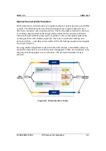
Page 76: ...grity of data transfers This includes the highly reliable trail protection mechanisms as well as equipment redundancy on specified critical units as described in Chapter 5 In addition advanced protection methods are available for the optical portions of the network 8 2 1 Optical Protection Due to the high capacity of traffic transmitted through CWDM systems protection is of utmost importance The X...

Page 77: ...fined as the protection channel The main benefit of OCH protection is its ability to choose the shortest path as the working path for each channel separately There are no dedicated working and protection fibers each fiber carries traffic with both working and protection signals in a single direction By using double transponder cards with built in OCH units a dual traffic path goes around the ring ...

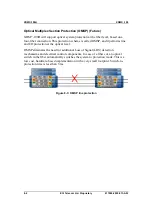
Page 78: ...called OMSP and it performs line and I O protection at the optical level OMSP eliminates the need for additional Loss of Signal LOS detection mechanisms and electrical control components In case of a fiber cut an optical switch in the fiber automatically switches the system to protection mode This is a low cost hardware based implementation with a very small footprint Switch to protection time is ...

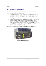
Page 79: ...U and the replacement NVM module containing the licensed hybrid option software Tributary Protection Unit Optical CWDM Unit TPU OCU mounted on top of the main XDM 100 shelf with four slots for supporting any mix of mux demux splitter coupler OADM or TPM modules and a Tributary Control TC module for carrying the power and control from the main shelf to the TPU OCU backplane Either one or two TPU OC...

Page 80: ...O UT IN MAI N2 OU T I N M A IN4 OUT I N C L IE NT 1 IN O UT C L IE N T 3 IN OUT C LIE N T 2 IN O UT C L I E N T4 IN OUT 8 50 1 3 1 0n m 8 5 0 1 3 1 0 n m Figure 8 5 TPU OCU shelf In addition to the standard set of modules supported in the XDM 100 shelf and described in Chapter 7 the XDM 100H also supports the following optical modules Table 8 1 I O modules Module No of slots Function Description C...

Page 81: ... without OSC filter Table 8 3 OADM modules Module Number of I O ports Function Description MO_COADM1AB_xx 1 1 Optical add drop of a single channel with 1310 nm built in OSC filter AB configuration MO_COADM2AB_xx 2 2 Optical add drop of 2 channels with 1310 nm built in OSC filter AB configuration 1 xx designates the channel dropped by the OADM 2 xx designates the group of two channels dropped by th...

Page 82: ...XDM 100H XDM 100 8 8 ECI Telecom Ltd Proprietary 417006 2005 013 A02 ...

Page 83: ...e at the input to telecommunication equipment operated by direct current 6 ETSI ETR 114 Functional Architecture of SDH Transport Networks 7 ETSI ETS 300 119 European Telecommunication Standard for Equipment Practice 8 ETSI ETS 300 147 Synchronous Digital Hierarchy Multiplexing Structure 9 ETSI ETS 300 232 Optical Interfaces for Equipment and Systems Relating to the Synchronous Digital Hierarchy 10...

Page 84: ... 192 Transport System Generic Criteria 19 GR 1400 CORE SONET Dual Fed Unidirectional Path Switched Ring UPSR Equipment Generic Criteria 20 GR 253 CORE Synchronous Optical Network SONET Transport Systems Common Generic Criteria 21 GR 326 CORE Generic Requirements for Singlemode Optical Connectors and Jumper Assemblies 22 GR 383 CORE COMMON LANGUAGE Equipment Codes CLEI Codes Generic Requirements fo...

Page 85: ...ommendation G 654 Characteristics of a Cut off Shifted Single mode Optical Fiber Cable 36 ITU T Recommendation G 655 Characteristics of a Non zero Dispersion Shifted Single mode Optical Fiber Cable 37 ITU T Recommendation G 661 Definition and Test Methods for the Relevant Generic Parameters of Optical Amplifier Devices and Subsystems 38 ITU T Recommendation G 662 Generic Characteristics of Optical...

Page 86: ... T Recommendation G 708 Sub STM 0 Network Node Interface for the Synchronous Digital Hierarchy SDH 51 ITU T Recommendation G 772 Protected Monitoring Points provided on Digital Transmission Systems 52 ITU T Recommendation G 774 G 774 n SDH Information Model 53 ITU T Recommendation G 783 Characteristics of SDH Equipment Functional Blocks 54 ITU T Recommendation G 784 Synchronous Digital Hierarchy S...

Page 87: ...itectures 66 ITU T Recommendation G 957 Optical Interfaces for Equipment and Systems relating to the Synchronous Digital Hierarchy 67 ITU T Recommendation G 958 Digital Line Systems Based on the Synchronous Digital Hierarchy for Use on Optical Fiber Cables 68 ITU T Recommendation G 959 1 Optical Transport Network Physical Layer Interfaces 69 ITU T Recommendation M 3010 Principles for a Telecommuni...

Page 88: ...ocuments XDM 100 A 6 ECI Telecom Ltd Proprietary 417006 2005 013 A02 79 RFC 2615 PPP over SONET SDH 80 RFC 2737 Entity MIB Version 2 81 RFC 2823 PPP over Simple Data Link SDL using SONET SDH with ATM like Framing ...

Page 89: ...R Bit Error Rate BIT Built In Test BLSR Bidirectional Line Switched Ring BPSR Bidirectional Path Switched Ring BSC Base Station Controller BTS Base Station Transceiver Subsystem CAPEX CAPital EXpenditure CCP Communication Control Panel CLE Customer Located Equipment CO Central Office CORBA Common Object Request Broker Architecture CPE Customer Premises Equipment CU Consolidation Unit DCC Digital C...

Page 90: ...work Manager eNM XDM XDM element management system EOW Engineering OrderWire ETSI European Telecommunication Standards Institute Fast Ethernet 100BaseT Ethernet at 100 Mbps FCU Fan Control Unit FE Fast Ethernet FICON Fiber Connection FN Functional Node FTP File Transfer Protocol GbE Gigabit Ethernet GFP Generic Framing Procedure GPRS General Packet Radio Service GSM Global System for Mobile Commun...

Page 91: ...n Ring MTNM MultiTechnology Network Management MXC Main Cross Connect Control NE Network Element NEL Network Element Layer NML Network Management Layer NMS Network Management System NT Network Termination NVM Non Volatile Memory OADM Optical Add Drop Multiplexer OHA OverHead Access OPEX OPerational EXpenditure OSC Optical Supervisory Channel OSNR Optical Signal to Noise Ratio OW Orderwire channel ...

Page 92: ...nguage SSM Synchronization Status Marker STM Synchronous Transfer Mode STM 1 Synchronous Transport Module 1 155 52 Mbps STM 4 Synchronous Transport Module 4 622 08 Mbps STM 16 Synchronous Transport Module 16 2488 32 Mbps STM 64 Synchronous Transport Module 64 9953 28 Mbps TCF Tributary Control and Fans TDM Time Division Multiplexing TM Terminal Multiplexer TMF TeleManagement Forum TMN Telecommunic...

Page 93: ...XDM 100 Glossary 417006 2005 013 A02 ECI Telecom Ltd Proprietary B 5 USB Universal Serial Bus VC Virtual Container VPN Virtual Private Network WAN Wide Area Network ...

Page 94: ...Glossary XDM 100 B 6 ECI Telecom Ltd Proprietary 417006 2005 013 A02 ...

Page 95: ...cessing 4 2 NE software and configuration backup 4 3 Cut through process eNM LightSoft 6 7 CWDM 1 1 1 3 3 1 4 9 8 1 8 2 8 4 8 5 8 6 D Data Applications 2 1 Ethernet capabilities 2 1 QoS 2 1 SLAs 2 1 Data Services 3 6 benefits and features 3 6 EIS M 3 6 Database Signature feature 6 7 Dense Wavelength Division Multiplexing See DWDM Dual Route Path Protection and Unidirectional Path Switched Ring UPS...

Page 96: ...ogies 2 2 STM 1 4 16 aggregation 2 2 Metropolitan Transmission Networks 3 2 Modular Architecture 3 2 Modules Aggregate 7 10 I O 7 9 MSPP 1 1 1 3 2 1 Multiplex Section Protection MSP and Line Protection 5 7 linear multiplex section protection MSP L and automatic protection switch APS 5 7 multiplex section shared protection ring MS SPRing and bidirectional line switched ring BLSR 5 8 Multiservice Pr...

Page 97: ...local interval clock 4 4 STM n 4 4 synchronization references 4 5 Topology Management 6 4 TPU I O Protection Shelf tributary control and fans module 7 5 tributary protection modules 7 4 Traffic and Cross connect 4 6 MXC matrix functions 4 6 Traffic Protection and Restoration equipment interface protection schemes 5 10 traffic protection schemes 5 10 Traffic Tasks non redundant configuration 3 5 re...

Page 98: ...Index XDM 100 I 4 ECI Telecom Ltd Proprietary 417006 2005 013 A02 ...

Reviews: