background image

Installation Guide

19

DVR-50 (G) 

5 Channel DVR Recorder

Alarm

Speed Alarm   


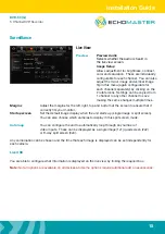
The speed alarm function can be turned on by ticking the 
enable box. You can also then configure the type of alarm 
reported (Alarm/Event).

Once enabled you can configure the speed setting, 
speed difference and alarm duration by clicking the  
trigger setup.

Base

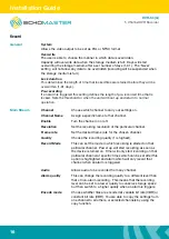
Using the linkage setup, it is also possible to link this alarm to one of the 2 available trigger outputs and 
additionally configure post-recording times in addition to linking the alarm to a particular camera.  The 
alarm snap feature is not functional on this product.

Post recording will continue to record locked video for the set time after the alarm has been cancelled.

Panel Alarm   

Requires additional devices.

IO Alarm 


The speed alarm function can be turned on by ticking the enable box.

You can also then configure the type of alarm reported (Alarm or Event).

Once enabled, you can configure the trigger setup to high or low voltage by clicking the trigger setup.  
Selecting high will mean that the trigger input on the chosen channel will need to go high (+12V) to trigger 
the alarm; Setting this to low will mean that the trigger needs to be taken to ground to trigger the alarm.

Using the linkage setup, it is also possible to link this alarm to one of the 2 available trigger outputs and 
additionally configure post-recording times in addition to linking the alarm to a particular camera.  The 
alarm snap feature is not functional on this product.

Post recording will continue to record locked video for the set time after the alarm has been cancelled.
It is possible to copy the settings from 1 alarm to any or all of the others using the copy feature.

Summary of Contents for DVR-50

Page 1: ...Installation Guide 1 Installation Manual 5 Channel Digital Video Recorder DVR 50 G ...

Page 2: ...age 9 Initial Setup Page 10 Menu Page 10 Main Menu Page 10 Home Screen Page 11 REC Search Page 12 Log Search Page 12 System Page 12 Log Out Page 12 Setup Page 12 Basic Setup Page 13 Regist Info Page 13 Device Info Page 13 Vehicle Info Page 13 Driver Info Page 13 Time Setup Page 13 General Page 13 Time sync Page 13 DST Page 13 Startup Page 13 On Off Page 13 Mode Page 13 Ignition Display Page 13 Tim...

Page 3: ...4 Network Application Other Setup Page 14 Surveillance Page 15 Live View Page 15 Preview Page 15 Preview Audio Page 15 Image Setup Page 15 Margins Page 15 Startup screen Page 15 Auto Loop Page 15 Live OSD Page 15 Record Page 16 General Page 16 System Page 16 Overwrite Page 16 Lock Duration Page 16 Pre recording Page 16 Main Stream Page 16 Channel Page 16 Channel Name Page 16 Enable Page 16 Resolut...

Page 4: ...age 16 Dual Stream Page 17 OSD Page 17 Position Page 17 IPC Setup Page 17 PTZ Page 17 Collection Page 18 General Page 18 Sensor Page 18 Sensor Number Page 18 Overwrite Page 18 OSD name Page 18 Serial Port Page 18 Speed Page 18 Navigation Page 18 Mileage Page 18 Source Page 18 Total Page 18 Base Value Page 18 Operation Page 18 Snap Setting Page 18 Alarm Page 19 Base Page 19 Speed Alarm Page 19 Pane...

Page 5: ... Page 20 Cover Page 20 Advanced Page 21 Acc Alarm Page 21 Electrifence Page 21 Maintenance Page 21 Config Page 21 File Data Page 21 Upgrade Page 21 Storage Page 21 Reset Page 21 Video Playback Page 22 References Page 23 Storage Capacity Page 23 Recording File Size Calculation Page 23 Contents ...

Page 6: ...rveillance Power On USB dongle inserted Recording in progress Operation Error Network connected SD Card Slots Alarm Indicator USB Port Front Panel Layout u Up to 256GB of flash storage u Quad analogue inputs u HD 5th channel input u Optional external trigger module DVR 50 TH u Optional GPS DVR 50 G u Lockable cover u DVR module u GPS Antenna DVR 50 G only u Power Cable u GX16 RCA adapters x 5 u Us...

Page 7: ...Installation Guide 7 DVR 50 G 5 Channel DVR Recorder Dimensions mm 167 3 157 8 140 1 146 3 125 125 ...

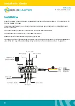
Page 8: ... the unit with 4 screws Connect the main power harness to 12V IGN and Ground Make all camera connections before powering up the unit Connect and route the GPS antenna DVR 50 G only to a position where it has a clear and unobstructed view of the sky Any metalwork or large wiring looms above the antenna can obstruct its operation A V OUT IPC 12V RED YELLOW IGN BLACK GND IPC Camera Camera CH4 A V Out...

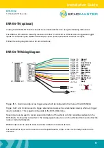
Page 9: ... In Trigger 6 In Trigger 5 In Trigger 4 In Trigger 3 In Trigger 2 In MIC SW IN 3 MIC 4 MIC 1 5V 2 1 2 21 22 DVR 50 TH Wiring Diagram Trigger IN 1 8 can be a high or low trigger value which is configured in the menu of the DVR 50 G Trigger Out 1 and 2 can be used to trigger external devices such as a telematics device when any trigger input is activated This is again configurable in the DVR 50 G me...

Page 10: ...recommended to carry out a format on all SD cards using the internal format function of the DVR before first use Menu Function Main Menu Using a right mouse click you can bring up the main options With these initial options you are able to select the individual channel display option or you are also able to choose 2 different split screen display options 4 way and 9 way split Note that in the 9 wa...

Page 11: ...isplayed for selecting specific video types all normal or alarm You can also select which channel to view channels without recorded data are greyed out Clicking search will provide the option to search by time and also channel multiple channels can be selected Clicking the or buttons will zoom in on the time bar graph allowing for very accurate time selection while clicking the or icons will scrol...

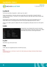
Page 12: ...layed next to it These will be shown in chronological order with the most recent displayed at the top of the list If the log is an alarm log then the related video file can be played by clicking the video icon to the right of the file System Clicking this icon will display all the relevant information about the DVR including connected modules server status DVR status environment and storage inform...

Page 13: ...mat time format and time zone Time sync You can set the time and also choose whether the time will remain synced via information received by GPS server or NTP server DST It is also possible to configure DST settings Once enabled you are able to set the DST On Off Mode Select whether to power cycle the unit according to ignition position timer or both ignition and timer Ignition delay Select a dela...

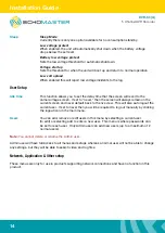
Page 14: ...ever then the screen will always remain on the current screen and never default back to the live view This will also auto logout the current user If set to never then you will be required to log out manually by clicking the logout icon in the main menu Users You can add remove or edit users in this menu by selecting a current user to edit or selecting add to enter a new user This menu is where pas...

Page 15: ...s for the left right top and bottom of the screen to ensure that it correctly fits your monitor Startup screen Set the default image display when the unit starts up single image or split screen You can also choose which cameras to display in this split screen mode Auto loop You can configure the unit to automatically loop through any number of video inputs These can be displayed as a single image ...

Page 16: ...annel Enable Turn the channel on or off Resolution Set the recording resolution of the particular channel Frame rate Set the desired frame rate for the chosen channel Quality Choose the recording quality 1 is highest Record Mode This can set the mode in which recording is started on that particular channel Power up will start recording as soon as the device is turned on Timer will only start recor...

Page 17: ...ation selected shown Click and drag the information to the desired area and click save IPC Setup Configure all settings when using the IPC HD cameras Please ensure that the IPC camera is connected before configuring any of these options Channels 1 3 are reserved for analog cameras and cannot be assigned to an IPC camera but either chan nel 4 or 5 can be used to display the video from a connected I...

Page 18: ...unit and source of the speed information can be configured Navigation Currently can only be set to GPS Mileage Source You are able to select the source of the mileage information Total Displays the total miles covered since last reset Base Value This is the initial starting value for the mileage counter when reset This can be useful if swapping out units as the mileage counter from the old unit ca...

Page 19: ...ces IO Alarm The speed alarm function can be turned on by ticking the enable box You can also then configure the type of alarm reported Alarm or Event Once enabled you can configure the trigger setup to high or low voltage by clicking the trigger setup Selecting high will mean that the trigger input on the chosen channel will need to go high 12V to trigger the alarm Setting this to low will mean t...

Page 20: ...gging the mouse across any of the grey highlighted grid To back out of this menu use the right mouse click Once happy with all the detection areas click OK and Save on the main screen Using the linkage setup it is also possible to link this alarm to one of the 2 available trigger outputs and additionally configure post recording times in addition to linking the alarm to a particular camera The ala...

Page 21: ...USB device using this menu Data can be exported in bulk all data or only between a certain period of time A USB hub can be used to simultaneously connect a USB drive and a mouse so that this operation can be carried out Upgrade The unit can be upgraded from this menu option when upgrades are released The upgrade file should be placed on the root folder of a USB device A USB hub can be used to simu...

Page 22: ...DVR Recorder Video Playback To playback stored video files you will need to download the Ceiba 2 software and user guide These can be downloaded from the following location http echomaster com index php controller attachment id_attachment 660 ...

Page 23: ...ording File Size Calculation The file size for each channel can be determined using the table above and the following calculation Recording Time seconds x Stream Kbps 8 1024 File size Mb For example 1 channel using D1 resolution at quality 2 recording for 1 hour 3600 x 1536 8 1024 675Mb ...

Page 24: ...EchoMaster com email support aampglobal com US tel 1 800 477 2267 East Coast 1 888 883 2790 West Coast email technical eu aampglobal com Europe 15500 Lightwave Drive Suite 202 Clearwater Florida 33760 Woolmer Way Bordon Hampshire United Kingdom ...

Reviews: