


7
Installing Wireless Devices
Careful planning is needed when locating the receivers and transmitters based
on the construction materials in the space and possibility of tenant’s furniture
disrupting the transmissions.
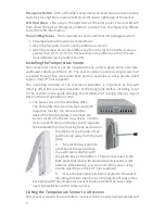
The temperature sensor should be installed in the space where the receiver is
mounted and connected to the temperature control equipment however the
signal will travel through material barriers.
Refer to the tables below for range considerations with building materials that
reduce the radio signal power.
Material
Attenuation
Wood
0 - 10%
Plaster
0 - 10%
Glass
0 - 10%
Brick
5 - 35%
MDF
5 - 35%
Ferro concrete
10 - 90%
Metal
90 - 100%
Aluminum
90 - 100%
Material
Radio Range-typical
Line of sight:
80’ (24m) corridors
Line of sight:
150’ (46m)open halls
Plasterboard:
80’ (24m) through 3 walls
Brick
33’ (10m) through 1 wall
Ferro concrete
33’ (10m) through 1 wall
Ceiling:
Not Recommended
Wireless System Layout Hints
•
Avoid locating transmitters and receivers on the same wall.
•
Avoid locating transmitters and receivers where the telegrams must
penetrate walls at acute angles. This increases the material the telegram
must pass through reducing the signal power.
•
Avoid large metal obstructions as they create radio shadows. Place
receivers in alternate locations to avoid the shadow or use repeaters to go
around the obstacle.
•
Do not locate receivers close to other high frequency transmitters. Leave
at least 3’ (1 m) between the receiver and any other source of interference
including, ballasts, LED drivers, computers, video equipment, Wi-Fi/LAN
routers, GSM modems and monitors. Transmitters are not affected by
these sources of interference.


