


4
Occupancy Button
- (RTS-2HS models only) Users can override a room occupancy
state by pressing the occupancy button on the lower right edge of the sensor.
LED Operation
- LEDs are on the right side of the solar panel. The red LED will
flash when the Link or Occupancy button is pressed. See Test Operating Modes
for further LED information.
Transmitting Values
- The temperature sensor will transmit a telegram when:
• 10 sample periods have been completed or
•
when the fan switch or occupancy button are used or
•
when the temperature value difference from the last transmitted value is
greater than 0.3°C, (0.5°F) or the humidity value difference from the last
transmitted value is greater than 3%.
Installing the Temperature Sensor
The temperature sensor can be mounted on any surface; glass, stone, concrete,
wallboard, cubicle partitions, etc. The sensor can be mounted using screws (not
supplied) through the removable back plate (2 keyholes or using double sided
tape or Velcro™ (not supplied).
The mounting location of the wireless transmitter is important as this will
directly affect the receivers reception of the telegrams. Before installing, refer
to the sections in the guide detailing the installation of wireless devices, layout
tips and the test operation modes.
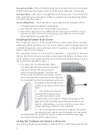
1. The sensor has a removable back plate.
The back plate has a security feature which
requires a tool for the removal of the
device from the backplate. To remove the
sensor, insert a flat head screw driver, into the
slot and exert torque on the key tab to separate
the backplate from the housing body as shown in
the photos. Once the tab is free,
pull the body away from the back
plate.
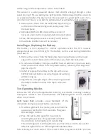
2.
Mount the back plate to
a bracket or the wall surface
in a vertical orientation with
the plastic key on the bottom. There are keyholes in the
back plate that mate with standard electrical box screw
patterns. Alternatively, you can mount the sensor using
double sided tape or Velcro® (not supplied).
3.
Once the back plate has been secured to the wall or
mounting bracket, align the two top alignment tabs on the
back plate with the temperature sensor body and press the lower edge
over the plastic key until it clicks in place.
Linking the Temperature Sensor to a Receiver
This process requires the controller or receiver to be mounted and powered and


