background image

21

EN

Part 2 – Attaching the Mount to the Display

IMPORTANT! 

Use extra care during this part of the installation. If possible, avoid placing your display 

facedown as it may damage the viewing surface.

NOTE: 

Your mount comes with a selection of different bolt diameters and lengths to accommodate 

a wide variety of display models. Not all of the hardware in the kit will be used.
1.  Determine the correct bolt to use by examining the back of your display:

A

  If the back of your display is fl at and the mounting holes are fl ush with the surface, you will use 

one the M4

×

12 Bolts (C) from the hardware kit.

B

  If the back of your display is curved, has a protrusion, or if the mounting holes are recessed, you 

will need to use one the M4

×

30 Bolts (D) and the Spacers (E).

2.  Attach the mount to the back of your display using the hardware identifi ed in Step 1. Make sure all 

screws are secure, but do not over-tighten.

NOTE: 

If the holes of the mount do not line up with the holes on your display, check to make sure 

that your display is VESA compatible. This mount can only be used with displays that are VESA 75 
or VESA 100 compatible.

Part 3 – Final Assembly

1.  To complete the installation, simply slide the mount with your display attached into the wall plate. 

The plastic tab at the top of the wall plate will click to indicate that the mount is secure.

2.  To remove the mount from the wall, push in on the plastic tab and carefully slide the mount upwards 

and out of the wall plate.

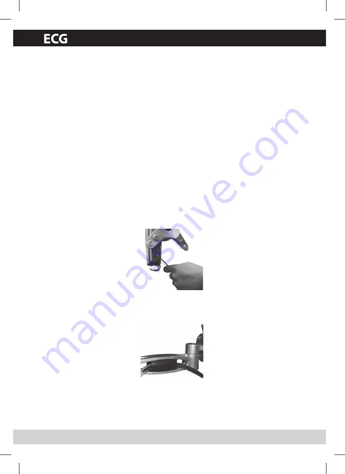
3.  For extra security and stability, tighten the set screw located on the wall plate (see illustration) using 

the S3 Allen Key (F) provided with the hardware kit. Remember to loosen the set screw before at-
tempting to remove the mount from the wall.

4.  To use the integrated cable management feature, fi rst remove the plastic covers located on the arm 

of the mount (see illustration). Route your cables through the arm and re-attach the plastic covers 
to hold them in place. Make sure to leave enough slack in the cables so that they are not pulled or 
pinched when you move the mount. You may also route the cables through the hook located at the 
bottom of the wall plate.

OPERATION AND ADJUSTMENT

1.  To adjust the tilt angle or rotate your screen, fi rmly grasp the sides of your display and carefully move 

it into position. If you fi nd the mount is too diffi cult to move or is too loose to hold your mount in 
position, adjust the three screws located directly behind the head of the mount using the S4 Allen 
Key (G) from the hardware kit (see illustration). Make sure you adjust all three screws evenly.

Summary of Contents for LD 1327 K

Page 1: ...ERZÁLNÍ DRŽÁK TV LD 1327 K Před uvedením výrobku do provozu si důkladně pročtěte tento návod a bezpečnostní pokyny které jsou v tomto návodu obsaženy Návod musí být vždy přiložen k přístroji NÁVOD K OBSLUZE ...

Page 2: ...ržák nainstalujte na bezpečné místo kde nedojde k ohrožení osob Po montáži nástěnného držáku a ploché obrazovky si prověřte dostatečnou stabilitu a bezpečnost provozu Kontrola by se měla opakovat v pravidelných intervalech nejméně 4x ročně Firma K B Progres a s neručí za škody způsobené nesprávným naistalováním nástěnného držáku a tím způsobené škody na zařízení případně zdraví VAROVÁNÍ 1 Před tím...

Page 3: ...í jednotlivého sloupku pro upevnění držáku použijte vysoce kvalitní podpovrchový de tektor 2 Označte si obě strany sloupku pro zjištění přesného středu viz obrázek Levý okraj sloupku Pravý okraj sloupku Střed sloupku 3 Nástěnnou desku umístěte na označený střed sloupku a pro vyrovnání použijte libelu 4 Označte dva otvory pro zajištění držáku a desku oddělejte 5 Vyvrtejte vodicí otvor ve všech ozna...

Page 4: ... příslušenství v sadě budou použity 1 Prozkoumáním zadní části televizoru určete šroub vhodný pro použití A V případě že je zadní část televizoru plochá a montážní otvory jsou zarovnány s povrchem po užijete šrouby M4 12 C ze sady příslušenství B V případě že je zadní tvar televizoru zaoblený má výstupek nebo když jsou montážní otvory zapuštěné bude potřeba použít šrouby M4 30 D a podložky E 2 Upe...

Page 5: ...klonění nebo otočení obrazovky pevně uchopte boční strany obrazovky a opa trně změňte polohu V případě že vám připadá pohyb držáku příliš obtížný nebo příliš volný povolte nebo přitáhněte tři šrouby umístěné přímo pod hlavou držáku pomocí imbusového klíče S4 G ze sady příslušenství viz obrázek Zkontrolujte vyrovnané dotažení všech tří šroubů 2 Natočení je možné provést jednoduše pohybem televizoru...

Page 6: ... a elektronických zařízení platí v členských zemích EU a dal ších evropských zemích se zavedeným systémem třídění odpadu Vyobrazený symbol na produktu nebo na obalu znamená že s produktem by nemělo být nakládáno jako s domovním odpadem Produkt odevzdejte na místo určené pro recyklaci elektrických a elektronických zařízení Správnou likvidací produktu zabráníte negativním vlivům na lidské zdraví a ž...

Page 7: ...LNY DRŽIAK TV LD 1327 K Pred uvedením výrobku do prevádzky si dôkladne prečítajte tento návod a bezpečnostné pokyny ktoré sú v tomto návode obsiahnuté Návod musí byť vždy priložený k prístroju NÁVOD NA OBSLUHU ...

Page 8: ...islé od modelu Nástenný držiak nainštalujte na bezpečné miesto a plochej obrazovky si preverte dostatoč nú stabilitu a bezpečnosť Kontrola by sa mala opakovať v pravidelných intervaloch najmenej 4x ročne Firma K B Progres a s neručí za škody spôsobené nesprávnou inštaláciou nástenného držiaku a tým spôsobené škody na zariadení a prípadne i zdraví VAROVANIE 1 Pred tým než sa pustíte do inštalácie u...

Page 9: ...notlivého stĺpika pre upevnenie držiaka použite vysoko kvalitný podpovrchový detektor 2 Označte si obe strany stĺpika pre zistenie presného stredu pozrite obrázok Ľavý okraj stĺpika Pravý okraj stĺpika Stred stĺpika 3 Nástennú dosku umiestnite na označený stred stĺpika a na vyrovnanie použite libelu 4 Označte dva otvory pre zaistenie držiaka a dosku odmontujte 5 Vyvŕtajte vodiaci otvor vo všetkých...

Page 10: ...íslušenstva v súprave nebudú použité 1 Preskúmaním zadnej časti televízora určite skrutku vhodnú na použitie A V prípade že je zadná časť televízora plochá a montážne otvory sú zarovnané s povrchom po užijete skrutky M4 12 C zo súpravy príslušenstva B V prípade že je zadný tvar televízoru zaoblený má výstupok alebo keď sú montážne otvory zapustené bude potrebné použiť skrutky M4 30 D a podložky E ...

Page 11: ...otočenie obrazovky pevne uchopte bočné strany obrazovky a opatrne zmeňte polohu V prípade že vám pripadá pohyb držiaka príliš ťažký alebo príliš voľný povoľte alebo pritiahnite tri skrutky umiestnené priamo pod hlavou držiaka pomocou imbusového kľúča S4 G zo súpravy príslušenstva pozrite obrázok Skontrolujte vyrovnané dotiahnutie všetkých troch skrutiek 2 Natočenie je možné vykonať jednoducho pohy...

Page 12: ...h a elektronických zariadení platí v členských krajinách EÚ a ďalších európskych krajinách so zavedeným systémom triedenia odpadu Vyobrazený symbol na produkte alebo na obale znamená že s produktom by sa nemalo nakladať ako s domovým odpadom Produkt odovzdajte na miesto určené na recykláciu elektrických a elektronických zariadení Správnou likvidáciou produktu zabránite negatívnym vplyvom na ľudské...

Page 13: ...DHALTERUNG LD 1327 K Vor der Inbetriebnahme dieses Geräts lesen Sie diese Anleitung und die darin enthaltenen Sicherheitshinweise sorgfältig durch DieBedienungsanleitungmussdemGerätimmerbeigelegtsein BEDIENUNGSANLEITUNG ...

Page 14: ...nen Sicherheiheitsabstand um das TV Gerätes abhängig von Model Die Halterung darf nicht an oder über Orten installiert werden an denen sich Halterung und des Flaschbildschirms sind diese auf ausrechende Festigkeit und Betriebssicherheit zu überprüfen Diese Prüfung ist in regelmäßigen Abständen zu wiederholen mindestens vierteljährlich Die Firma K B Progres a s wirk keine Gewährleistung für unsachg...

Page 15: ...ie einen hoch wertigen Baustreben Detektor 2 Markieren Sie beide Seiten der Strebe zur Ermittlung der genauen Mitte siehe Abbildung Linker Rand der Strebe Rechter Rand der Strebe Mitte der Strebe 3 Positionieren Sie die Wandplatte an der markierten Mitte der Strebe Verwenden Sie zum Ausrichten die eingebaute Wasserwaage 4 Markieren zwei Löcher für die Befestigung der Halterung und entfernen Sie di...

Page 16: ...ernsehgerät WICHTIG Seien Sie bei diesem Teil der Installation besonders aufmerksam Vermeiden Sie es nach Möglichkeit das Fernsehgerät mit dem Bildschirm nach unten aufzulegen da die Bildschirmfläche dadurch beschädigt werden könnte ANMERKUNG Der Halterung sind Schrauben von verschiedener Dicke und Länge zur Befestigung einer Vielzahl verschiedener Gerätemodelle beigefügt Nicht alle Teile des Zubeh...

Page 17: ...er integrierten Kabelbündelung nehmen Sie zunächst die Kunststoffabdeckung am Arm der Halterung ab siehe Abbildung Ziehen Sie die Kabel durch den Arm und befestigen Sie die Kunststoffabdeckung wieder Kontrollieren Sie ob alle Kabel genügend Bewegungsfreiheit haben sodass Sie beim Bewegen der Halterung nicht herausgezogen oder eingeklemmt werden Die Kabel können auch durch den Haken im unteren Teil...

Page 18: ...fsstelle oder bei kommunalen Sondermüll Sammelstellen abgeben ENTSORGUNG DES PRODUKTS NACH ABLAUF DER LEBENSDAUER Entsorgung gebrauchter elektrischer und elektronischer Geräte gilt in den EU Mitglieds staaten und anderen europäischen Ländern mit Mülltrennungssystem Das auf dem Produkt oder auf der Verpackung abgebildete Symbol bedeutet dass das Produkt nicht mit dem Hausmüll entsorgt werden darf G...

Page 19: ...MONITOR WALL MOUNT LD 1327 K Read this user s manual and the safety instructions con tained in it carefully before putting the product into opera tion The user s manual must always come with the product USER S MANUAL ...

Page 20: ...ry safety clearence around the TV set depends on the model The bracket may not be mounted at or above locations where persons could stand Once you have mounted the bracket and the flat screen check that they are sufficiently secure and safe to use You should repeat this check at regular intervals at least every three monts K B Progres a s provides no warranty coverage and is not liable for damage re...

Page 21: ...g the Drywall Screws A from the hardware kit Do not over tighten these screws Part 1B Installing the Wall Plate Concrete IMPORTANT For safety reasons the concrete wall must be capable of supporting the combined weight of the mount and the display 1 Place the wall plate against the wall in the desired location and level it using the integrated bubble level 2 Mark the two holes for securing the moun...

Page 22: ...y slide the mount with your display attached into the wall plate The plastic tab at the top of the wall plate will click to indicate that the mount is secure 2 To remove the mount from the wall push in on the plastic tab and carefully slide the mount upwards and out of the wall plate 3 For extra security and stability tighten the set screw located on the wall plate see illustration using the S3 Al...

Page 23: ...or take to a place defined by the municipality for the disposal of dangerous wastes DISPOSAL OF PRODUCTS AT END OF LIFETIME The disposal of used electric and electronic devices valid in EU member states and other Euro pean countries with an implemented system for sorting waste The displayed symbol on the product or the packaging means that the products should not be handled as household waste Hand ...

Page 24: ...pert cz zelená linka 800 121 120 zelená linka 800 121 120 ZStudio 2009 Dovozce neručí za tiskové chyby obsažené v návodu k použití výrobku Dovozca neručí za tlačové chyby obsiahnuté v návode na použitie výrobku Der Importeur haftet nicht für Druckfehler in der Bedienungsanleitung des Produkts The importer takes no responsibility for printing errors contained in the product s user s manual Distribu...

Reviews: