background image

4

1-INTRODUCTION

First of all, we would like to thank you for choosing E.C.A brand. E.C.A. Proteus Premix condensing boilers 
have  been  designed  to  meet  for  an  efficient,  safe  and  comfortable  central  heating  and  hot  water 
requirement. The Proteus Premix condensing boilers can possibly use natural gas or LPG according to the 
desired fuel preference. There is no standard LPG models. LPG usage is only possible after gas conversion 
in the field. 

HM Model (Combi Boiler)    : 

Both Central Heating (CH) and Domestic Hot Water (DHW). 

HCH Model (Heat Only)     : 

Only for Central Heating (CH). 

HST Model (System Boiler) : 

Both for Central Heating (CH) and Domestic Hot Water (DHW) with external 

storage tank (not included). 

The assembly and usage information of 24/30/35 kW Proteus Premix condensing boilers are available in 
this manual. Detailed information have been provided in the guide regarding the technical specification of 
the boiler, selection of the  boiler location, fitting  its  water, gas, flue  and  electric supply connections, gas 
conversion, maintenance information and solving of possible failures. Please carefully read the manual in 
order to benefit from all the features of your boiler. 

The Benchmark Checklist and Service Record Card are located at the back of the Operating Manual. 

The Benchmark Checklist must be filled by gas safe engineer during installation. 
Operating  Manual  and  Service  Manual  must  be  handed  over  the  user  for  future 
operations. 

Service Record Card must be filled by gas safe engineer and handed over the user 

after each service operation and annual maintanence. 

1.1 

Installer’s Responsibility 

The installer is responsible for the installation and initial start-up


of the boiler. Instructions are given below. 

Check Operating and Service manuals and follow instructions before installation.

Carry out installation in compliance with the prevailing legislation and standarts.

Be sure that the system is flushed and inhibitor added.

Only gas safe engineer must operate the boiler.

Explain the user about installation and operation of boiler.

Fill the Comissioning Checklist.

Give all Operating and Service manuals to user.

The warranty certificate must be registered by gas safe engineer within 30 days after installation.

Summary of Contents for PROTEUS PREMIX PPR Series

Page 1: ...PROTEUS PREMIX PPR 24 30 35 HM HST HCH PROTEUS PREMIX CONDENSING BOILER OPERATING MANUAL INSTALLATION COMISSIONING...

Page 2: ...urers and installers The purpose is to ensure that customers are provided with the correct equipment for their needs that it is installed commissioned and serviced in accordance with the manufacturer...

Page 3: ...from Ambient Air Type C 23 7 3 Mounting the Combi Boiler 23 8 CONNECTIONS 24 8 1 Flue Connections 24 8 2 Condensate Discharge Connection 27 8 3 Gas and Water Connections 28 8 4 Electrical Connections...

Page 4: ...rsion maintenance information and solving of possible failures Please carefully read the manual in order to benefit from all the features of your boiler The Benchmark Checklist and Service Record Card...

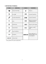
Page 5: ...arameter Adjustment DHW Domestic Hot Water Reset NTC Negative Temperature Coefficient sensor Winter Mode RCD Residual Current Device Summer Mode ECV Emergency Control Valve Solar Panel Mode SEDBUK Sea...

Page 6: ...gineer as soon as possible Do not place and use flammable and explosive liquid or materials around the boiler Keep materials such as water foam away from electrical connections during operations such...

Page 7: ...t E C A for proper cabine sizes If boiler is located in an unheated area it must be connected to mains switched on and pressure of installation should be within operation range so that freeze protecti...

Page 8: ...and similar purposes Primarily for use in plugs BS6891 Installation of low pressure gas pipe work up to 28mm R1 BS5546 Installation of gas hot water supplies for domestic purposes EN12828 Central hea...

Page 9: ...oiler in operation late at night keeping water temperature of the heating circuit at low levels will ensure saving If you feel that the room temperature is high the radiator valves should be closed in...

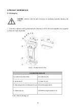
Page 10: ...cartonboard with dimensions of 735 x 345 x 490 HxWxD mm supported by upper and lower styrofoams Figure 1 Package Exploded View Table 4 Standard Package List STANDARD PACKAGE LIST 1 3 Bottom Top Styrof...

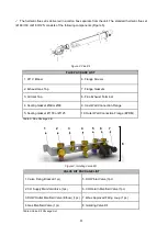
Page 11: ...Exhaust Terminal 4 Sealing Gasket 60 or 80 9 Inner Wall Connection Flange 5 Sealing Gasket 100 or 125 10 Outer Wall Connection Flange EPDM Table 5 Flue Package List Figure 3 Isolating Valve Kit VALVE...

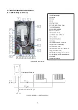
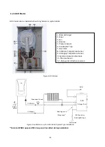
Page 12: ...3 Bar Safety Valve 9 Pressure Sensor 10 Condensate Trap 11 Plated Heat Exchancer 12 Gas Valve 13 Return Manifold 14 Pump 15 Flexible Connection Hose 16 Expension Vessel 8L 17 Rainwater Hose 18 Rainwat...

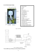
Page 13: ...ety Valve 9 Pressure Sensor 10 Condensate Trap 11 Gas Valve 12 Return Manifold 13 Pump 14 Flexible Connection Hose 15 Expension Vessel 8L 16 Expansion Tank Holder Bracket 17 Rainwater Hose 18 Rainwate...

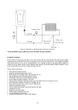
Page 14: ...added during installation 1 Main Exchanger 2 Mixer 3 Fan 4 Silencer 5 Pressure Sensor 6 Condensate Trap 7 Gas Valve 8 CH Return Temperature Sensor 9 CH Supply Temperature Sensor 10 Ignition Ionisatio...

Page 15: ...ly ensured These safety systems are Flame Failure Safety System Boiler Over Heat Safety System 95 C DHW Domestic Hot Water Over Heat System 71 C High Water Pressure Protection System 3 bar Low Water P...

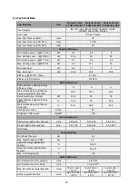
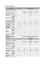
Page 16: ...iency Class A A A Water Heating Energy Efficiency Class Load Profile Only HM A XL A XL A XL Rated Heat Output Prated kW 24 5 30 35 Seasonal Space Heating Energy Efficiency 92 2 92 92 9 Water Heating E...

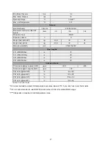
Page 17: ...288 Flue Lenghts C13 60 100 Max m 10 C13 80 125 Max m 20 C33 60 100 Max m 10 C33 80 125 Max m 20 Emission Values CO emission max capacity G20 ppm 250 300 CO emission min capacity G20 ppm 50 C02 ratio...

Page 18: ...al Space Heating 92 2 92 92 9 Water Heating 83 6 82 8 82 8 Sound Power Level Lwa Indoors dB 49 Specific Precautions for Assembly Installation and Maintanence All specific precautions for installation...

Page 19: ...on from fiche of solar device III The value of the mathematical expression 294 11 Prated whereby Prated is related to the preferential space heater IV The value of the mathematical expression 115 11 P...

Page 20: ...ckage The energy efficiency of the package of products provided for in this fiche may not correspond to its actual energy efficiency once installed in a building as this efficiency is influenced by fu...

Page 21: ...dimensioning of the products in relation to building size and characteristics I The value of the water heating energy efficiency of the combination heater expressed in II The value of the mathematica...

Page 22: ...o not install your boilers in locations that will be exposed to direct sunlight Sunlight can cause color change on the exterior of your boiler over time Ambient temperature of boiler s installation lo...

Page 23: ...ptable dimensions from the terminal to obstructions an ventilation openings must obey national and local requirements All horizontally fitted ducts air flue should be fitted 2 or 3 upwards incline to...

Page 24: ...e inner pipe facing outwards should be inclined upward and the fresh air pipe outer pipe should be inclined downward When the original flue set is installed parallel to the ground the exhaust gas pipe...

Page 25: ...or horizontal pipe 60 B Below an air vent 60 H Below the distance grille from the outside of the building 30 C Below rain channel 30 I Distance from the inner corner of the building 100 D Under the b...

Page 26: ...Flue Kit 7006990073 80 125 CCB Flue Adapter 7006990067 80 125 76 cm CCB Horizontal Hermetic Flue Kit 7006990065 60 100 CCB Sloping Roof Adapter 7006990066 60 100 CCB Deck Roof Adapter 7006990061 60 10...

Page 27: ...connected at least 2 5 downwards incline to ensure to a good flow It can not rise at any point along its length Condensate discharge must be installed correctly otherwise operation of the boiler will...

Page 28: ...de according to the national and local instructions The boiler must be earthed and a standard 230 V AC 50 Hz supply is required CAUTION Disconnect power supply to prevent electrical shock before conne...

Page 29: ...stat Programmable Digital Room Thermostat CM707 7006901313 Wireless 7006901501 Digital Room Thermostat DT90 7006902502 Digital Room Thermostat Wireless Programmable 7006902046 On Off Wired Room Thermo...

Page 30: ...stat the bridged cable connection on the back of the control panel is removed and the outer air sensor is connected to free sockets on the terminal Figure 21 OTC Curve It can be provided as an option...

Page 31: ...imer must be performed certainly by gas safe engineer Room thermostat connection is installed by after removing bridge circuit Outdoor sensor is installed by connecting its cables to free terminals Ti...

Page 32: ...ESET Check water pressure on pressure indicator frequently and ensure that the pressure is between 1 5 and 2 bar when system is cold If the pressure drops frequently it means that there is a water lea...

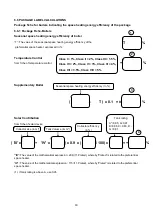
Page 33: ...light will be OFF after 1 minute Anti freeze function remains active 11 CONTROL PANEL Figure 23 Control Panel View 11 1 Functions of Buttons The control panel consists of the relevant elements as sho...

Page 34: ...e unit will switch to Comfort mode C Domestic Hot Water Increase Temperature Button The temperature of the domestic water can be increased up to 65 C thanks to the domestic water temperature increase...

Page 35: ...tive 11 3 3 Winter mode Radiator Heating If the boiler in the standby position is set to the winter position it will heat the water in the heating circuit until the domestic water is needed In the win...

Page 36: ...e anti freeze function helps protect your boiler it does not protect your installation If the boiler will not be operated for a while in places where there is risk of freezing then it is necessary to...

Page 37: ...nic card may be failed 1 Press reset button 2 If the error is still present or persists after reset notify gas safe engineer E09 Valve Feedback Error The gas valve may be failed 1 Press reset button 2...

Page 38: ...is still present or persists after reset notify gas safe engineer F07 Over Temperature Error for Flue Gas It occurs when the temperature of the flue gas exceeds 95 C 1 Notify gas safe engineer F13 Re...

Page 39: ...et notify gas safe engineer F52 Error on Temperature Sensor for DHW Temperature sensor for domestic water might be defective 1 Notify gas safe engineer F53 Error on Temperature Sensor for Flue Gas The...

Page 40: ...or where in our sole opinion repairis not economic arrange to replace the boiler 6 We will not accept or reimburse the costs of any third party who undertakes any work carried on the product or fits p...

Page 41: ...e provided or if we are unable to obtain clear and safe access to the property or product or if we have reason to believe that the health and safety of our engineer cannot be guaranteed f If chargable...

Page 42: ...re that the heating system is clean Power flushing is the most efficient and effective method of cleaning a central heating system The principle is to create a powerful fresh water flow under controll...

Page 43: ...43 15 ANNEXES 15 1 Characteristic Curve of Water Pressure Height of The Pump Pump Head Flow Rate 15 60 for 24 3 kW Models Graph 2 15 70 for 35 kW Model Graph 3...

Page 44: ...6990251 IGNITION ELECTRODE CABLE 7006990120 HIGH VOLTAGE CABLE 7006990121 LOW VOLTAGE FAN CABLE 7006990174 LOW VOLTAGE FLOW SENSOR CABLE 7006990320 GAS ORRIFICE 24 kW 7006990688 GAS ORRIFICE 30 kW 700...

Page 45: ...ired Thermostatic radiator valves Fitted Not required Automatic bypass to system Fitted Not required Boiler interlock Provided ALL SYSTEMS s instructions Yes What system cleaner was used What inhibito...

Page 46: ...mpany name Telephone No Gas safe register No Record At max rate CO ppm AND CO At min rate Where Possible CO ppm AND CO Comments Signature SERVICE 06 Date Engineer name Company name Telephone No Gas sa...

Page 47: ...s m Mustafa Kemal Bulvar No 13 45030 MAN SA 90 236 213 00 21 90 236 213 08 SALES TECHNICAL SUPPORT Call Center Tel 44 800 640 9988 Office Tel 44 20 3978 1212 Act vat ng your quarantee s qu ck and s m...

Reviews: