background image

Chengdu Ebyte Electronic Technology Co.,Ltd

E104-BT30 User Manual

Copyright ©2012–2019

Chengdu Ebyte Electronic Technology Co.,Ltd

2-5

14

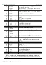
1V35-SMPS

P

Module 1.35V power output, external decoupling capacitor is recommended,
see Recommended circuit for details

15

VREGENA

BLE

I

Bluetooth module power-on / power-off control pin, high level is effective.
Note that the module needs to be initialized before powering on.

16

VCHG

P

Internal charger input, usually connected to VBUS, see Typical application
circuit for details

17

CHG_EXT

P

External battery charger control (reserved function)

18

VBAT_SE

P

Battery charge sensing input (reserved function)

19

VBAT-IN

P

Battery power input pin, cannot exceed 3.6V, otherwise the module will be
damaged

20

GND

P

Ground, connect to power reference ground

21

USB-DN

I/O

USB cable negative (reserved function)

22

USB-DP

I/O

USB cable positive (reserved function)

23

PIO18

I/O

General-purpose I / O (reserved function)

24

PIO21

I/O

General-purpose I / O (reserved function)

25

PIO6

I/O

General-purpose I / O (reserved function)

26

PIO1

I/O

Next song Key input, high level is effective

27

PIO8

I/O

Previous song Key input, high level is effective

28

VDD-PADS

-1

P

Input and output port power supply 1, usually 1.8V power supply connection

29

1V8-SMPS

P

Module 1.8V power output, external decoupling capacitor is recommended, see
4.2 Recommended circuit for details

30

VDD-PADS

-2

P

Input and output port power 2, usually 1.8V power connection

31

PIO7

I/O

Key input, high level effective, long press to continuously

increase;

32

PIO9

I/O

Play / Pause

Key input, high level effective

33

PIO0

I/O

Volume -

Key input, high level effective, long press to continuously

decrease;

34

MIC-AN

I

Channel A line or microphone input negative

35

MIC-AP

I

Channel A line or microphone input positive

36

MIC-BIAS

I

Microphone bias

37

LINE-BN

I

Channel B line input negative

38

LINE-BP

I

Channel B line input positive

39

SPK-RN

O

Right channel speaker output negative

40

SPK-RP

O

Right channel speaker output positive

41

SPK-LN

O

Left channel speaker output negative

42

SPK-LP

O

Left channel speaker output positive

43

GND

P

Ground, connect to power reference ground

pay attention:

The function description of the above pins is only for the default program functions of our company. If you need other

functions, please contact us for customization. For the self-developed pin functions, please refer to the official user manual of
CSRA64215.

Summary of Contents for E104-BT30

Page 1: ...E104 BT30 User Manual CSRA64215 Wireless Audio Module...

Page 2: ...parameter 2 2 1 Electrical performance parameters 3 2 2 Size and pin definition 4 3 Quick start 6 4 Hardware circuit design and requirements 7 4 1 Hard design 7 4 2 Recommended application circuit 8 5...

Page 3: ...n product to quickly achieve high quality Bluetooth audio transmission and enjoy wireless music And the module supports APTX APTXLL ACC and other high quality sound effects 1 2 Features Bluetooth V4 2...

Page 4: ...tooth protocol standard frequency band Powe r consu mptio n Not connected current mA 0 5 8 Bluetooth is discoverable Connected unplayed current mA 10 14 Bluetooth is connected but no music is playing...

Page 5: ...g load pin 4 PIO16 I O Module audio output indication pin high level is effective 5 PIO3 I O SPI MISO debug load pin 6 SPI PCM I SPI PCM input selection 0 PCM PIO interface 1 SPI 7 PIO2 I O SPI MOSI d...

Page 6: ...ous song Key input high level is effective 28 VDD PADS 1 P Input and output port power supply 1 usually 1 8V power supply connection 29 1V8 SMPS P Module 1 8V power output external decoupling capacito...

Page 7: ...ect AUX_OUT output power Connect the 3 5mm headphones here Power amplifier circuit If the user has a 3W speaker you can directly connect the two terminals of the power amplifier circuit Key control ci...

Page 8: ...on the blue light flashes quickly after pressing both buttons simultaneously for 2 seconds Enter slave mode PLAY button NEXT button the blue light flashes quickly after pressing both buttons simultane...

Page 9: ...mance It is recommended to keep them away from the module according to the strength of the interference If necessary appropriate isolation and shielding can be done Assume that there are traces with l...

Page 10: ...eflow Soldering Temperature Profile Feature Curve feature Sn Pb Assembly Pb Free Assembly Solder Paste Solder paste Sn63 Pb37 Sn96 5 Ag3 Cu0 5 Preheat Temperature min Tsmin Minimum preheating temperat...

Page 11: ...tance Size Package Interface Hz m mm E104 BT30 V1 0 CSRA64215 2 402 2 485G 50 25 16 2 0 SMD Stereo R L 8 Disclaimer This manual is as comprehensive and detailed as possible based on the existing mater...

Page 12: ...vision history Version Date Description Issued by 1 0 2019 10 22 Initial version 1 1 2019 10 29 Format adjustment Ren 1 2 2020 03 23 Ren 10 About us Sales hotline 4000 330 990 Tel 028 61399028 Support...

Reviews: