Chengdu Ebyte Electronic Technology Co.,Ltd.
Copyright ©2012–2021
,
Chengdu Ebyte Electronic Technology Co.,Ltd.
2
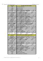
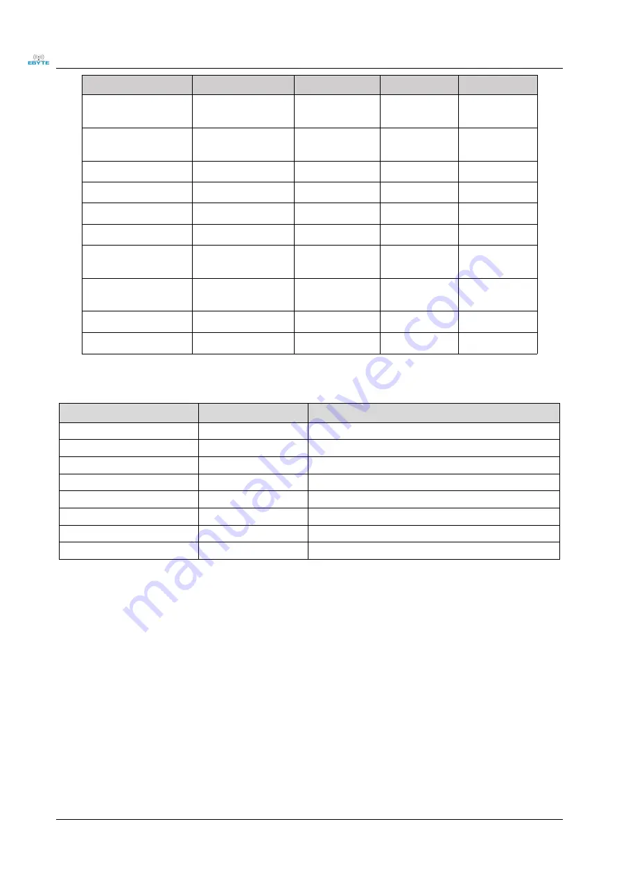
category
Emission current
110
120
130
mA
Receive current
13
14
15
mA
Turn off the current
2.4
2.5
2.6
uA
Transmit power
21.0
21.2
21.8
dBm
Receive sensitivity
-139
-140
-140
dBm
TCXO crystal
32
32
32
MHZ
TCXO crystal voltage
configuration
1.8
1.8
3.3
V
Recommended
operating band
850
868/900/915
925
MHZ
The supply voltage
2.5
3.3
3.7
V
Communication level
2.5
3.3
3.7
V
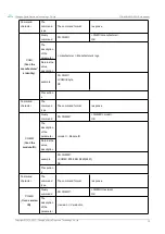
main parameters
Ddescription
remark
Reference distance
5600m
Clear and open, antenna height 2 meters, air rate 1kbps
Crystal frequency
32MHz
-
Modulation
LoRa(recommendation) GFSK Mode
,
FLRC Mode
,
LoRa Mode
Packing method
SMD
-
Interface method
1.27mm
-
Communication Interface
SPI
0
~
10Mbps
Dimensions
20*14mm
-
Antenna interface
IPEX/stamp hole
the equivalent impedance is about 50Ω
2.3 Parameter description
When designing the power supply circuit for the module, it is often recommended to reserve more than 30% margin,
and the whole machine is conducive to long-term stable operation;
The current required at the moment of launch is relatively large, but often because the launch time is extremely short,
the total energy consumed may be smaller;
When the customer uses an external antenna, the impedance matching degree between the antenna and the module
at different frequency points will affect the size of the emission current to different degrees;
The current consumed when the RF chip is in a purely receiving state is called the receiving current. Some RF chips
with communication protocols or the developers have loaded some self-developed protocols on the whole machine,
which may cause the receiving current of the test to be too large;


