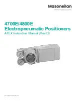
EP100 Master Instruction
3
_____________________________________________________
D00002-C-04
1 METHOD OF OPERATION
1.1 General
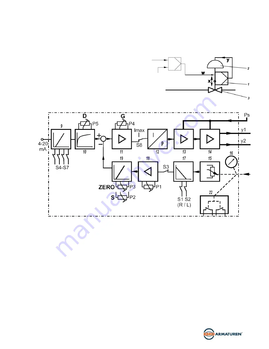
The intelligent positioner EP100
1
and the pneumatic
actuator
2
form a control loop with the setpoint value
w
(from master controller or control system), the output
pressure
y
and the position x of the actuator on valve
3
.
The positioner can be attached to both linear actuators
and rotary actuators.
Actuators with spring force are controlled by a single
acting positioner.
Actuators without spring force are controlled by a
double acting positioner. The positioner can be
operated by means of switches and potentiometers.
For the supply air, we recommend a filter regulator..
.
1.2 Block diagram
1.3 Operation
The supply of the electronics unit is diverted from
the current signal 4 to 20 mA at the input.
The current value is measured and is suited in
input circuit
9
to the desired input range (control
action or split range) via switches S4 - S7. In
circuit
10
the signal is provided with an adjustable
time constant settable via potentiometer
P5.
The resulting internal signal is guided to the analog
control circuit
11
, the gain of which is adjustable
via potentiometer P4. The output of the control
circuit drives the electromechanic converter (IP
module)
12
, which controls the analog single
acting or double acting pneumatic amplifier
14
through the preampifier
13
. The output of the
amplifier
14
is the output pressure y (y1,y2) to the
actuator. The pneumatic amplifiers are supplied
with supply air Ps 1.4 to 6 bar (20 to 90 psig).
The position x of the actuator is measured by the position
sensor (conductive plastic potentiometer)
15
. The desired
direction of rotation is set in
17
via switches S1 and S2. The
SPAN is suited to the stroke / rotation angle range via
potentiometer P2, while ZERO is set in
19
via potentiometer
P3. With switch S3 potentiometer P1 provides an internal
zero adjustment in
18
carried out by the manufacturer
(service function). The resulting feedback signal is guided to
control circuit 11.
The IP module receives its maximum drive current via switch
S8 enabling checking of the funktion of the pneumatic unit.
The position x of the actuator is independently displayed at
the mechanical travel indicator
16
.
The mechanical limit switch
22
(optional) enables
independent alarm signals.


