background image

Chapter 7


28 

tapping on the screen and releasing from the screen. 


Tone 

Drag the bar to adjust the frequency of the sound effect. 

The minimize value is 200 and maximum value is 5000. 


Duration 

Drag the bar to adjust how long the “Beep” sound will be. 

The minimize value is 10 and maximum value is 50. 


The selected option will be in black. 


6.2. Screen Calibration 

1. Click the drop menu next to the Calibration button to select calibration 

mode. 


4 points, mode 1

 – rectangular four-point calibration 

4 points, mode 2 

– rhombic four-point calibration 


2. Click 

Calibration

 button to enter the calibration screen. 
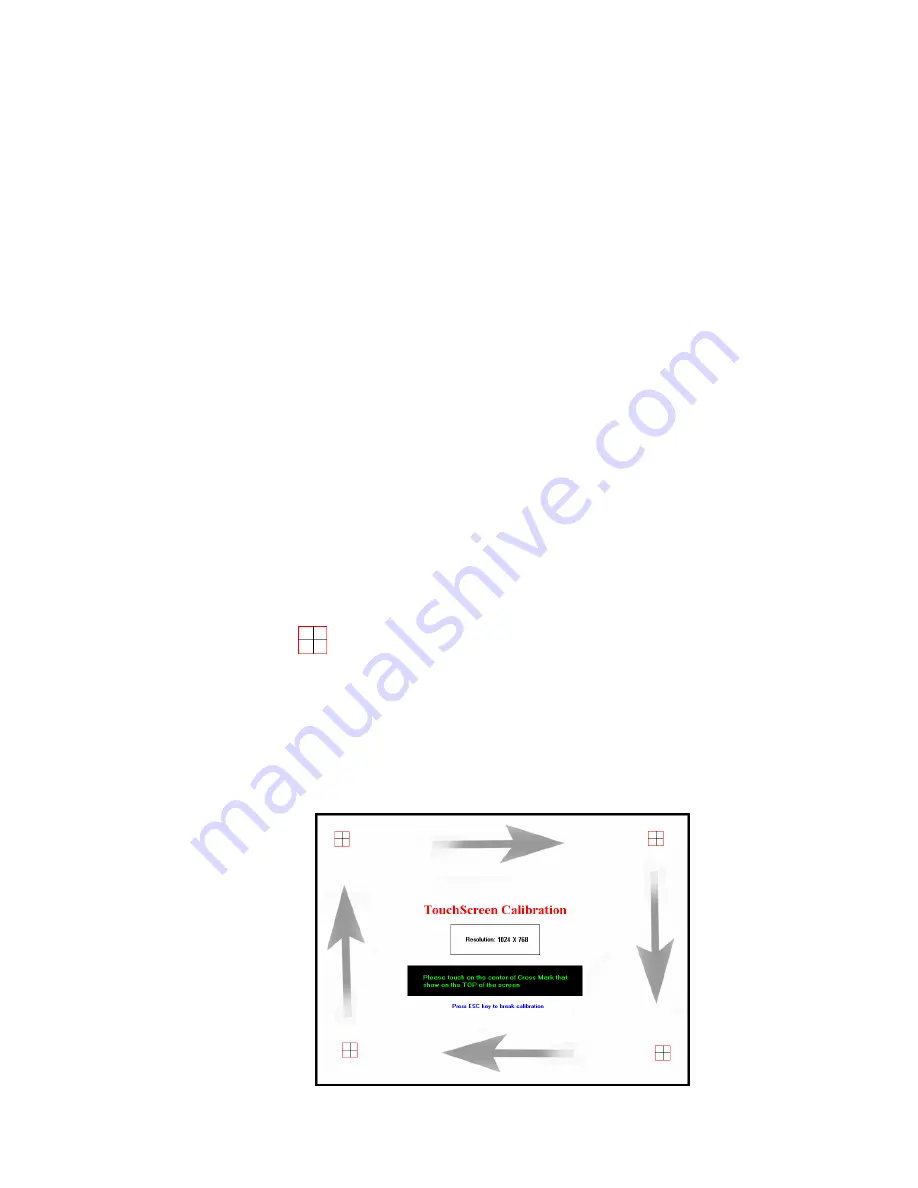
 

4 points, mode 1 

a. The 

  mark shows on the Left-up corner. 

b. Follow the instruction in green to touch the center of Cross Mark. 

c. When the instruction turns into yellow, releasing the tapping from the 

screen. 

d. Follow the instruction in green to touch the center of Cross Mark. 

e. Repeat Step 2 – Step4 to finish the calibration procedure. 


Summary of Contents for POS60-8B-C1G

Page 1: ...User s Manual POS60 5B C1G POS60 2B C1G POS60 8B C1G...

Page 2: ......

Page 3: ...uipment generates uses and can radiate radio frequency energy and if not installed and used in accordance with the instructions may cause harmful interference to radio communications However there is...

Page 4: ...rective 2002 96 EC concerning waste electrical and electronic equipment WEEE The Directive determines the framework for the return and recycling of used appliances as applicable throughout the Europea...

Page 5: ...2 Keyboard assembly Installation Keyboard MSR and iButton 13 Driver and Utility Installation 15 5 1 Before the installation 15 5 2 Chipset Software Installation 15 5 3 VGA Driver Installation 17 5 4...

Page 6: ...Contents iv 7 2 Serial Port 1 2 3 4 30 7 3 PS2 COM5 31 7 4 Cash Drawer Port RJ 11 31 Specification 33...

Page 7: ...or service business With Intel ULV Celeron M 1GHz w o L2 Cache and Intel 852GM ICH4 onboard SolidPOS 60 series could be at your service 24 X 7 and minimize maintenance required Combined and equipped w...

Page 8: ...4x USB 2 0 1 x RS 485 422 232 3 x RS 232 Gigabit Ethernet port RJ 45 and cash drawer port RJ 11 equipped Peripherals 31 key keyboard customer display MSR cash drawer and iButton expandable Microsoft...

Page 9: ...Chapter 2 3 2 Unpacking the Box Verify that the box contains the following items 1 Device X 1 2 Driver and utility CD X 1 3 Power Adaptor X 1 4 Power Cord X 1 5 HDD screws...

Page 10: ...p 3 1 Quick Tour Front View LED Indicator The Power indicator will glow green when power is on The HDD indicator will blink green when the HDD is accessed The LAN indicator will blink green when trans...

Page 11: ...5 Back Panel I O Note The I O panel is covered by the front cover For details about removing the from cover please see Note For details of I O ports on the back panel please refer to Chapter 7 I O De...

Page 12: ...lation 1 Loosen the tool free screw anticlockwise on the bottom of the device as shown below 2 Remove the back cover from the device by pulling back 3 Loosen and remove two screws on the middle cover...

Page 13: ...apter 3 7 4 Pull the middle cover in the direction as shown below 5 Bend the middle cover softly in the direction as shown below to remove it from the device 6 Install the four HDD screws as shown bel...

Page 14: ...Chapter 3 8 7 Connect the IDE cable to the HDD 8 Connect the power cable to the HDD 9 Install the HDD to the device...

Page 15: ...Chapter 3 9 10 Tighten the five screws as shown below 3 3 RAM installation 1 Align and insert the new RAM into the slot 2 Push both ends of the RAM down until the ejectors snap into place...

Page 16: ...Connect the four pin connector of the power adapter into the DC 19V socket on the I O panel and the other end into the grounded wall outlet properly 2 Press and hold the power switch until the power i...

Page 17: ...1 Loosen the two tool free screws anticlockwise on the bottom of the device as shown below 2 Remove the front covert assembly 3 Disconnect the green speaker jack and the black multi function connector...

Page 18: ...he four screw holes of the customer display to the brown yellow screw holes of the LCD panel assembly and then tighten screws by 1 Phillips screwdriver as shown below 7 Connect the RJ 45 connecter to...

Page 19: ...Cable to the COM port of the device 10 Connect the speaker cable t and the multi function connecter to the device as shown below 4 2 Keyboard assembly Installation Keyboard MSR and iButton 1 Connect...

Page 20: ...Chapter 4 14 2 Install the keyboard assembly to the device 3 Tighten the two screws as shown below...

Page 21: ...ribed below are based on Microsoft Windows XP 1 Connect an external USB CDROM drive to the USB port and insert the driver CD and turn on the device The program autoruns and displays the DRIVER BANK sc...

Page 22: ...Chapter 4 16 2 Click Next 3 1 Click Next 3 2 Read the License Agreement carefully and click Yes 4 Click Next...

Page 23: ...Chapter 4 17 5 1 Select restart your computer right now or later 5 2 Click Finish 5 3 VGA Driver Installation 1 Click Graphic Driver 2 Click VGA Driver for WIN2K XP...

Page 24: ...Chapter 4 18 3 Click Next 3 1 After files extracted click Next on the welcome screen 4 Read the License Agreement carefully and click Yes and then the installation starts...

Page 25: ...19 5 1 Select restart your computer right now or later 5 2 Click Finish 5 4 LAN Driver Installation 1 Click RTL81x0 LAN Driver 1 1 On the welcome screen click Next 1 2 Click Install to begin the inst...

Page 26: ...Chapter 4 20 3 Click Finish 5 5 Audio Driver Installation 1 Click AC 97 Audio Driver 2 Configures new software installation...

Page 27: ...Chapter 4 21 3 Click Configure Anyway 4 AC 97 drivers begins to install 5 1 Select restart your computer right now or later 5 2 Click Finish...

Page 28: ...Chapter 4 22 5 6 Wireless LAN Driver Installation 1 Click AC 97 Audio Driver 2 On the welcome screen click Next and then the installation begins...

Page 29: ...Chapter 4 23 3 1 Select restart your computer right now or later 3 2 Click Finish...

Page 30: ...rtual button setting dialogue box c Feedback Sound Open the feedback sound setting dialogue box d Power Save Open the power down timer adjustment dialogue box e Calibration Switch to calibration scree...

Page 31: ...ox shows The selected option will be in black Virtual Button Option Under Virtual Button Option group box there are four options Stream Mode Under this mode all mouse button simulation will be disable...

Page 32: ...p down List If the Drag Drop Mode under Virtual Button Option group box is select the drop down menu below the Enable On option will be enabled Automatic Mode Select this option the Right Button Funct...

Page 33: ...to enable or disable the beep sound effect for toggle on and toggle off 6 3 Feedback Sound Click Feedback Sound button the dialogue box shows Feedback Sound Option Silence No Sound No any sound effect...

Page 34: ...k the drop menu next to the Calibration button to select calibration mode 4 points mode 1 rectangular four point calibration 4 points mode 2 rhombic four point calibration 2 Click Calibration button t...

Page 35: ...touch the center of Cross Mark e Repeat Step 2 Step4 to finish the calibration procedure 3 When the calibration procedure is completed the message shows To save the new calibration click Yes to resto...

Page 36: ...al information about all I O ports as followings 7 1 Power Connector PIN Description PIN Description 1 19V 3 GROUND 2 19V 4 GROUND 7 2 Serial Port 1 2 3 4 COM Port 1 2 3 4 PIN Description PIN Descript...

Page 37: ...tion PIN Description 1 GND 6 PC_CLK KEYBOARD 11 CTS 2 5V 7 KB_DAT 12 RTS 3 RXD 8 KB_CLK 13 DSR 4 TXD 9 RI 5V 12V 14 DCD 5 PC_DAT KEYBOARD 10 DTR 15 KB_EN 7 4 Cash Drawer Port RJ 11 Connector PIN Descr...

Page 38: ...Chapter 7 32 Cash Drawer Control Status Address Value Open 280H Bit 4 10H Close 280H Bit 4 00H Read Status 281H Bit 0...

Page 39: ...Chapter 8 33 8 Specification...

Page 40: ...Device HDD 1 x 3 5 IDE HDD Compact Flash 1 x Slot Type II I O Ports Serial 4 x RS 232 DB 9 5V 12V RI Parallel 0 USB 4 x USB2 0 PS2 Mouse 0 PS2 Keyboard 0 LAN 1 x RJ45 Gigabit Ethernet Cash Drawer 1 x...

Reviews: