


Operating instructions
K3G630-AP01-90
`
II 2G Ex db eb ib IIB T3 Gb
IBExU14ATEX1122 X /05
`
Translation of the original operating instructions
54007-4-8670
Regular cleaning of the device prevents imbalance caused by
deposits, for example.
7.2 Safety inspection
NOTE
High-voltage test
The integrated EMC filter has Y capacitors. The tripping current
is exceeded when AC testing voltage is applied.
→ Test the device with DC voltage when you perform the
legally required high-voltage test. The voltage to be used
corresponds to the peak value of the AC voltage required by
the standard.
7.3 Maintenance interval
What to check
How to check
How often
What action?
Corrosion
Visual inspection At least every
3 months
When there is
heavy
corrosion that
impairs the
explosion
protection, e.g.
in gap
surfaces,
replace the
device.
Contact
protection
cover for
intactness or
damage
Visual inspection At least every
6 months
Repair or
replacement of
device
Device for
damage to
blades and
housing
Visual inspection At least every
6 months
Replacement of
device
Fastening the
cables
Visual inspection At least every
6 months
Fasten
Insulation of
cables for
damage
Visual inspection At least every
6 months
Replace wires
Impeller for
wear/deposits/
corrosion and
damage
Visual inspection At least every
6 months
Clean impeller
or replace device
Tightness of
cable gland
Visual inspection At least every
6 months
Retighten,
replace if
damaged
Condensation
drainage holes
for clogging,
where necessary
Visual inspection At least every
6 months
Open holes
Welds for crack
formation
Visual inspection At least every
6 months
Replace device
Cable routing
(fastening)
Visual inspection At least every
6 months
Fasten cables
Cleaning and
preventive
maintenance
Visual inspection At least every
3 months
Remove dirt,
clean device
Ball bearings
for smooth and
noiseless
movement free
of play
acoustic and/or
manual check
by turning rotor
when switched
off, vibration test
At least every
3 months
Replace the
device in the
event of noise,
stiffness or
bearing play.
Have motor
bearings
replaced by
ebm-papst.
Vibration test
See Vibration
test section
At least every
6 months
Cleaning,
repair or
replacement of
device
Check gap
dimensions
See Gap
dimensions
section
At least every
3 months
Replacement of
device
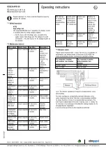
7.4 Vibration check
Regular checks must be made to ensure that the fan is not operated at
impermissibly high vibration levels. On the basis of ISO 14694, the
maximum permissible vibration velocities are specified as follows:
Fan connected to system
with isolation from vibration
Fan connected to system
without isolation from
vibration
Vibration velocity
Vibration velocity
max. 6.3 mm/s
max. 4.5 mm/s
Fig. 9: The vibration velocities are measured in radial direction at the
stator bushing.
The motor bearings are provided with permanent lubrication at the
factory. Experience has shown that under normal operating conditions
the grease therefore only has to be renewed after several years. The
motor must be deactivated in the event of bearing noise. To remedy this,
the motor has to be exchanged or the defective bearings replaced by the
ebm-papst Service department.
A record is to be kept of the routine inspections performed.
Item no. 54007-5-9970 · ENU · Change 272968 · Approved 2022-11-23 · Page 18 / 18
ebm-papst Mulfingen GmbH & Co. KG · Bachmühle 2 · D-74673 Mulfingen · Phone +49 (0) 7938 81-0 · Fax +49 (0) 7938 81-110 · [email protected] · www.ebmpapst.com


