background image

Operating instructions

K3G310-AZ88-02

Translation of the original operating instructions

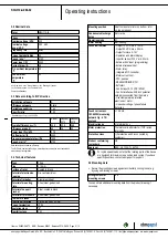
3.6 Transport and storage conditions

;

Use the device in accordance with its protection type.

Max. permissible
ambient motor temp.
(transp./ storage)

+80 °C

Min. permissible
ambient motor temp.
(transp./storage)

-40 °C

3.7 Electromagnetic compatibility

EMC interference
immunity

Acc. to EN 61000-6-2 (industrial
environment)

EMC interference
emission

Acc. to EN 61000-6-3 (household
environment)

If several devices are switched in parallel on the mains side so
that the line current of the arrangement is in the range of 16 - 75
A, then this arrangement conforms to IEC 61000-3-12 provided
that the short-circuit power S

sc

at the connection point of the

customer system to the public power system is greater than or
equal to 120 times the rated output of the arrangement.
It is the responsibility of the installation engineer or operator/
owner of the device to ensure, if necessary after consultation
with the network operator, that this device is only connected to
a connection point with a S

sc

value that is greater than or equal

to 120 times the rated output of the arrangement.

4. CONNECTION AND START-UP

4.1 Connecting the mechanical system

CAUTION
Cutting and crushing hazard when removing the fan
from the packaging

→ Carefully remove the fan from its packaging. Make sure to

avoid any shock.

→ Wear safety shoes and cut-resistant safety gloves.

CAUTION
Heavy load when taking out the device

Bodily harm, e.g. back injuries, are possible.
→ Two people should remove the device out of its packaging

together.

;

Check the device for transport damage. Damaged devices must no
longer be installed.

;

Install the undamaged device according to your application.

4.2 Connecting the electrical system

DANGER
Electric voltage on the device

Electric shock
→ Always install a protective earth first.
→ Check the protective earth.

DANGER
Incorrect insulation

Risk of fatal injury from electric shock
→ Use only cables that meet the specified installation

requirements for voltage, current, insulation material, load etc.

→ Route cables such that they cannot be touched by any

rotating parts.

DANGER
Electrical load (>50 µC) between mains wire and
protective earth connection after switching of the supply
when switching multiple devices in parallel.

Electric shock, risk of injury
→ Make sure that sufficient protection against accidental contact

is provided.
Before working on the electrical connection, the
connections to the mains supply and PE must be shorted.

CAUTION
Electrical voltage

The fan is a built-in component and features no electrically
isolating switch.
→ Only connect the fan to circuits that can be switched off with

an all-pole separating switch.

→ When working on the fan, you must switch off the

installation/machine in which the fan is installed and secure it
from being switched on again.

NOTE
Interferences and failures are possible

Maintain a distance to the power supply line when routing the
control lines of the device.
→ Ensure a sufficiently large clearance.

Recommendation: clearance > 10 cm (separate cable
routing)

Item no. 50655-5-9970 · ENG · Revision 82542 · Release 2014-05-08 · Page 6 / 12

ebm-papst Mulfingen GmbH & Co. KG · Bachmühle 2 · D-74673 Mulfingen · Phone +49 (0) 7938 81-0 · Fax +49 (0) 7938 81-110 · [email protected] · www.ebmpapst.com

Summary of Contents for K3G310-AZ88-02

Page 1: ...itted to install the device to carry out a test run and to perform work on the electrical installation 1 3 Basic safety rules 1 1 3 Basic safety rules Any safety hazards stemming from the device must be re evaluated once it is installed in the end device Observe the following when working on the unit Do not make any modifications additions or conversions to the device without the approval of ebm p...

Page 2: ...rotor and impeller can be injured Secure the device against accidental contact Before working on the system machine wait until all parts have come to a standstill DANGER Flying parts Missing safety devices may cause balancing weights or broken fan blades to be ejected at high speeds causing bodily harm Take appropriate safety measures WARNING Rotating device Long hair loose items of clothing and j...

Page 3: ...ice in the following ways is particularly prohibited and may cause hazards Operating the device with an imbalance e g caused by dirt deposits or icing Operation in medical equipment with a life sustaining or lifesaving function Operation with external vibrations Moving solids content in flow medium Painting the device Connections e g screws coming loose during operation Opening the terminal box du...

Page 4: ...ozzle with bleeder connection for pressure relief k factor 116 2 Cable diameter min 4 mm max 10 mm tightening torque 4 0 6 Nm 3 Tightening torque 3 5 0 5 Nm Item no 50655 5 9970 ENG Revision 82542 Release 2014 05 08 Page 4 12 ebm papst Mulfingen GmbH Co KG Bachmühle 2 D 74673 Mulfingen Phone 49 0 7938 81 0 Fax 49 0 7938 81 110 info1 de ebmpapst com www ebmpapst com ...

Page 5: ...s B Humidity class F4 1 Mounting position Shaft horizontal or rotor on bottom rotor on top on request Condensate discharge holes Rotor side Operation mode S1 Motor bearing Ball bearing Technical features Output 10 VDC max 10 mA Output 20 VDC max 50 mA Output for slave 0 10 V Operation and alarm display Input for sensor 0 10 V or 4 20 mA External 24 V input programming External release input Alarm ...

Page 6: ...vice out of its packaging together Check the device for transport damage Damaged devices must no longer be installed Install the undamaged device according to your application 4 2 Connecting the electrical system DANGER Electric voltage on the device Electric shock Always install a protective earth first Check the protective earth DANGER Incorrect insulation Risk of fatal injury from electric shoc...

Page 7: ...4 Residual current operated device Only universal type B or B RCD protective devices are permitted Like frequency inverters RCD protective devices cannot provide personal safety while operating the device When switching on the power supply of the device pulsed charge currents from the capacitors in the integrated EMC filter can lead to the RCD protective devices triggering without delay We recomme...

Page 8: ...nstalled upright 4 4 Factory settings Factory settings with which the device is pre set by ebm papst Control mode parameter set 1 PWM controlling Control mode parameter set 2 PWM controlling Fan device adress 01 Max PWM 100 Min PWM 5 Save set value to EEPROM Yes Set value control Analogue linear Control function parameter set 1 Positive heating Control function parameter set 2 Positive heating Ite...

Page 9: ...en pin or applied voltage 5 50 VDC disabling bridge to GND or applied voltage 1 VDC reset function triggers software reset after a level change to 1 VDC SELV KL 3 8 Din2 Digital input 2 parameter set switch 1 2 according to EEPROM setting the valid used parameter set can be selected via bus or via digital input DIN2 Parameter set 1 open pin or applied voltage 5 50 VDC Parameter set 2 bridge to GND...

Page 10: ...e fan for foreign objects and remove any that are found Apply the nominal voltage to the voltage supply Start the device by changing the input signal 4 8 Switching off the device Switching off the device during operation Switch off the device via the control input Do not switch the motor e g in cyclic operation on and off via power supply Switching off the device for maintenance work Switch off th...

Page 11: ...cal blockage Mains supply voltage faulty Check mains supply voltage restore power supply Important The error message resets automatically The device starts up again automatically without advance warning Faulty connection De energise correct connection see connection diagram Motor winding broken Replace device Thermal overload protector responded Allow motor to cool off locate and rectify cause of ...

Page 12: ...he protective casing against accidental contact for damage and to ensure that it is intact Visual inspection At least every 6 months Repair or replacement of the device Check the device for damage to blades and housing Visual inspection At least every 6 months Replacement of the device Mounting the connection lines Visual inspection At least every 6 months Fasten Check the insulation of the wires ...

Reviews: