

Operating instructions
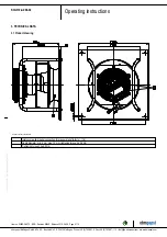
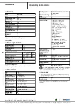
K3G310-AZ88-02
Translation of the original operating instructions
If you have any other problems, contact ebm-papst.
6.1 Cleaning
NOTE
Damage to the device during cleaning.
Malfunction possible
→ Do not clean the device using a water jet or high-pressure
washer.
→ Do not use any cleaners containing acids,
bases or solvents.
→ Do not use any pointed or sharp-edged objects to clean.
6.2 Safety test
NOTE
High-voltage test
The integrated EMC filter contains Y capacitors. Therefore, the
trigger current is exceeded when AC testing voltage is applied.
→ Test the device with DC voltage when you carry out the
high-voltage test required by law. The voltage to be used
corresponds to the peak value of the AC voltage required by
the standard.
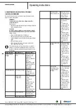
What has to
be tested?
How to test?
Frequency
Which
measure?
Check the
protective
casing against
accidental
contact for
damage and to
ensure that it is
intact
Visual inspection At least every
6 months
Repair or
replacement of
the device
Check the
device for
damage to
blades and
housing
Visual inspection At least every
6 months
Replacement
of the device
Mounting the
connection lines
Visual inspection At least every
6 months
Fasten
Check the
insulation of
the wires for
damage
Visual inspection At least every
6 months
Replace wires
Impeller for
wear/deposits/
corrosion and
damage
Visual inspection At least every
6 months
Clean or
replace impeller
Tightness of
screwed cable
gland
Visual inspection At least every
6 months
Retighten,
replace if
damaged
Condensate
discharge
holes for
clogging, as
necessary
Visual inspection At least every
6 months
Open bore holes
Item no. 50655-5-9970 · ENG · Revision 82542 · Release 2014-05-08 · Page 12 / 12
ebm-papst Mulfingen GmbH & Co. KG · Bachmühle 2 · D-74673 Mulfingen · Phone +49 (0) 7938 81-0 · Fax +49 (0) 7938 81-110 · [email protected] · www.ebmpapst.com


