


Operating instructions
K3G310-AZ88-02
Translation of the original operating instructions
3.2 Nominal data
Motor
M3G112-IA
Phase
3~
Nominal voltage / VAC
400
Nominal voltage
range / VAC
380 .. 480
Frequency / Hz
50/60
Type of data definition
ml
Speed / min
-1
4100
Power input / W
3240
Current draw / A
4.9
Min. ambient temperature
/ °C
-25
Max. ambient
temperature
/ °C
40
ml = Max. load · me = Max. efficiency · fa = Running at free air
cs = Customer specs · cu = Customer unit
Subject to alterations
3.3 Data according to ErP directive
Installation category
A
Efficiency category
Static
Variable speed drive
Yes
Specific ratio
*
1.02
*
Specific ratio = 1 + p
fs
/ 100 000 Pa
Actual
Request
2013
Request
2015
Overall efficiency η
es
/ %
56.8
52.8
56.8
Efficiency grade N
62
58
62
Power input P
ed
/ kW
3.19
Air flow q
v
/ m³/h
4025
Pressure increase total p
sf
/ Pa
1535
Speed n / min
-1
4120
Data definition with optimum efficiency.
The ErP data is determined using a motor-impeller combination in a standardised
measurement configuration.
3.4 Technical features
Mass
25 kg
Size
310 mm
Surface of rotor
Coated in black
Material of electronics
housing
Die-cast aluminium
Material of impeller
Aluminium sheet
Material of mounting
plate
Sheet steel, galvanised
Material of support
bracket
Steel, coated in black
Material of inlet nozzle
Sheet steel, galvanised
Number of blades
7
Direction of rotation
Clockwise, seen on rotor
Type of protection
IP 54
Insulation class
"B"
Humidity class
F4-1
Mounting position
Shaft horizontal or rotor on bottom; rotor
on top on request
Condensate discharge
holes
Rotor-side
Operation mode
S1
Motor bearing
Ball bearing
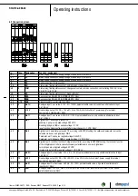
Technical features
- Output 10 VDC, max. 10 mA
- Output 20 VDC, max. 50 mA
- Output for slave 0-10 V
- Operation and alarm display
- Input for sensor 0-10 V or 4-20 mA
- External 24 V input (programming)
- External release input
- Alarm relay
- Integrated PID controller
- Motor current limit
- PFC, passive
- RS485 MODBUS RTU
- Soft start
- Control input 0-10 VDC / PWM
- Control interface with SELV potential
safely disconnected from the mains
- Over-temperature protected
electronics / motor
- Line undervoltage / phase failure
detection
Touch current acc.
IEC 60990 (measuring
network Fig. 4, TN
system)
<= 3.5 mA
Electrical leads
Via terminal box
Motor protection
Thermal overload protector (TOP) wired
internally
Protection class
I (if protective earth is connected by
customer)
Product conforming
to standard
CE
Approval
EAC; UL 1004-7 + 60730
For cyclic speed loads, note that the rotating parts of the device
are designed for maximum one million load cycles. If you have
specific questions, contact ebm-papst for support.
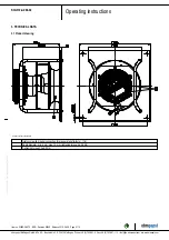
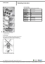
3.5 Mounting data
;
Secure the mounting screws against accidentally coming loose (e.g.
by using self-locking screws).
Strength class for
mounting screws
8.8
You can obtain additional mounting data from the product drawing if
necessary.
Item no. 50655-5-9970 · ENG · Revision 82542 · Release 2014-05-08 · Page 5 / 12
ebm-papst Mulfingen GmbH & Co. KG · Bachmühle 2 · D-74673 Mulfingen · Phone +49 (0) 7938 81-0 · Fax +49 (0) 7938 81-110 · [email protected] · www.ebmpapst.com


