


4
IT
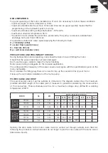
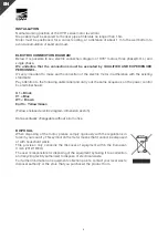
INSTALLAZIONE
La posizione normale di funzionamento è verticale.
Il cavo di discesa deve essere fissato alla tubazione ad una distanza intervallata di 1.5m.
Il motore, per essere raffreddato correttamente, deve rimanere ad una distanza di almeno 1m dal
fondo per evitare l’accumulo di sabbia e/o di fango.
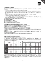
SCHEMA/COLLEGAMENTO ELETTRICO
Di seguito vengono evidenziati lo schema elettrico dei motori OY3” trifase ad avviamento diretto
(D.O.L.) e monofase.
Si precisa che il collegamento deve essere effettuato ESCLUSIVAMENTE DA PERSONALE
SPECIALIZZATO.
Il collegamento a terra deve essere sempre eseguito e deve essere fatto inconformità alla normativa
vigente.
Prestare attenzione alla seguente marcatura dei cavi per poi trasferirla sull’estremità degli stessi nel
quadro elettrico di comando:
U1=Nero
V1=Blu
W1=Marrone
Terra=Giallo/Verde
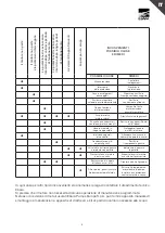
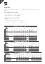
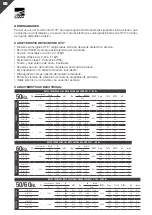
(Seguono in allegato gli schemi elettrici/scheda dimensionale)
Ebara Pumps Europe S.p.A. si riserva di cambiare le caratteristiche tecniche senza preavviso.
SMALTIMENTO
Nel demolire il motore attenersi rigorosamente alle disposizioni in vigore nel
proprio paese. Questo simbolo presente sul motore indica che non può essere
smaltito insieme ai rifiuti domestici.
Questa disposizione riguarda solamente lo smaltimento delle apparecchiature nel
territorio dell’Unione Europea (2012/19/UE). È responsabilità dell’utente smaltire
le apparecchiature consegnandole presso un punto di raccolta designato al
riciclo e allo smaltimento di apparecchiature elettriche.
Per ulteriori informazioni relative ai punti di raccolta delle apparecchiature,
contattare l’ente locale per lo smaltimento dei rifiuti, oppure il negozio presso il
quale è stato acquistato il prodotto.
Summary of Contents for OY3 Series
Page 28: ...28 RU 1 5 1 OY3 U1 V1 W1 Ebara Pumps Europe S p A 2012 19...
Page 29: ...29 RU Ebara Ebara Pumps Europe S p A...
Page 30: ...30...
Page 31: ...31...
Page 33: ......
Page 35: ...35...


