background image


- 9 - 

2. Pipes 

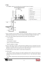
The installation must be done according to the arrangement shown in the Figure: 


Fig.2 Installation view 

1. Make sure that the suction and delivery ducts do not transmit  any stresses to the pump, by  installing 

sufficiently strong supports. If this is not done, the pump could become misaligned and even break. 

2. Fit any check valves (between the pump and the delivery valve) in the following cases: 

-  In very long pipes. 

-  If the head is high. 

-  If the operation is automatic. 

-  When you fill a tank under pressure. 

-  When the operation is in parallel. 

3. Mount air relief valves, if required, in those parts of the  installation where it is impossible to avoid the 

formation  of  air  bubbles.  However,  they  must  not  be  fitted  at  points  where  the  pressure  is  less  than 

atmospheric pressure, since the valve would suck in air rather than expel it. 

4. To reduce the effect of a water hammer, mount a check valve with spring. 

5. Suction systems: 

-  The  bottom  end  of  the  suction  pipe  must  remain  submerged  and  at  a  depth  of  at  least  twice  the 

diameter of the pipe (2D) and at a distance from the bottom of 1 time to 1 and a half times the diameter 

(1~1.5 D). 

-  Fit a bottom valve with a filter at the beginning of the suction pipe to prevent the entry of any foreign 

bodies. 

1


Pump


2


Motor


3


Pipe Support


4


Flexible Joint


5


Check valve


6


Gate valve


7


Foot valve


8


Eccentric reduction


1~1.5D 

2D 

1~1.5D 

Summary of Contents for GS

Page 1: ...tion 11 3 Accessories 24 5 Electrical maintenance 12 10 Disassembly and Assembly 25 6 Operation 12 1 Disassembly 25 1 Preparation for operation 12 2 Assembly 31 2 Operation Stopping 13 CAUTION Thank y...

Page 2: ...and fire Turn OFF the power switch before inspecting or repairing the pump Not doing so could result in the pump starting up suddenly in auto operation exposing personnel to danger Do NOT operate the...

Page 3: ...l be injury danger In addition it may lead to pipe damage danger due to pump vibration Install the coupling guard after the couplings are aligned In addition during pump operation don t be close to th...

Page 4: ...ironment deteriorated insulation in the electric motor drive or control panel may lead to electric leakage electric shock and fire When the pump is out of use for prolonged periods such as the wintert...

Page 5: ...and Operation item Otherwise It may cause unsmooth pump operation motor burning or idle operation Avoid the pump operation without priming and permitting air to enter the handled liquid Otherwise the...

Page 6: ...that the pump is as ordered by referring to the nameplate Fig 1 2 Confirm that no damage has occurred during transportation Check all nuts and bolts to confirm that they are not loose 3 Confirm that a...

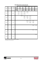
Page 7: ...ons are on Table 1 Table 1 Standard specifications G S G SD Tem perature D ensi ty V i scosi ty I m pel l er ShaftSeal M echani calSeal G l and P acki ng M echani calSeal B eari ng Shi el d B al lB ea...

Page 8: ...inspection 2 Provide an enclosure around the pump or take some other effective measures to prevent unauthorized personnel from coming near it 3 Install the pump in a location where it is near a water...

Page 9: ...ts of the installation where it is impossible to avoid the formation of air bubbles However they must not be fitted at points where the pressure is less than atmospheric pressure since the valve would...

Page 10: ...tling and overhauls Install the suction pipe with an upward gradient towards the pump to avoid the formation of air bubbles 3 Alignment If a simple elastic coupling is used adjust by placing tapered l...

Page 11: ...cable gland so as to ensure the degree of protection indicated on the nameplate Avoid any mechanical stress being transferred to the motor terminals Comply with the current and frequency limits indic...

Page 12: ...s surfaces will be hot and you could get burned if you touch them Do not cover the motor with a blanket or cloth Doing so could over heat the motor setting a fire 1 Preparation for operation Note Aft...

Page 13: ...ischarge valve to start cycle operation 4 Check for abnormal pressure current vibration or noise Keep the cocks of the pressure gauge and compound gauge closed except when taking measurements These ga...

Page 14: ...eakage value is moderate according to Table 2 d Checking table of the water leakage value as a standard Table 2 The water leakage value as a standard Inner diameter of gland packing mm Initial operati...

Page 15: ...OFF before inspecting or repairing the pump Not doing so could result in the pump starting up suddenly in auto operation exposing personnel to danger Caution If the pumped liquid is hot water keep yo...

Page 16: ...ctor It may cause bolts to be lost 5 For gland packing specification make sure the water leakage value is moderate according to Table 2 and preventing over tightening and uneven tightening gland packi...

Page 17: ...ide the pump could freeze causing damage to the pump Accordingly in such situations provide thermal insulation to prevent the water from freezing 4 When the pump is out of use for three months or more...

Page 18: ...0 315 125 200 100 250 65 315 150 200 125 250 80 315 100 315 100 250L 80 315L 80 400 125 250L 100 315L 100 400 150 250 125 315 125 400 150 315 150 400 150 400L 125 500 200 400 150 500 200 500 M echani...

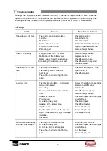
Page 19: ...mechanical seal The pump has no flow rate The pump does not turn The delivery valve is closed or half closed The suction head is too high for the pump Check that the impeller is free Open the valve C...

Page 20: ...time with the valve closed or half closed Replace the bearings Avoid such a situation Open the valve or stop the pump Excessive operating vibration and noise Fault in installation Bearings damaged Fl...

Page 21: ...Star Delta commutation Check the power supply Correct the power surges Align and or replace the bearing Remove foreign bodies Connect the pump correctly Correct the cabling Motor overheating Appearanc...

Page 22: ...t Wait until the temperature goes down Check the temperature before touching Stop the pump and proceed very carefully Stop the pump and proceed very carefully Always fit protection guards Keep your di...

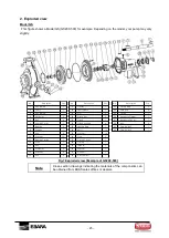
Page 23: ...orm AB 1 17 Gasket 1 33 Casing Ring 2 2 Shaft 1 18 Shaft Sleev e 1 34 Spring Pin 2 3 Key form AA 1 19 Nut 2 35 Casing 1 4 Deflector 2 20 Gland Bolt 2 36 Handhole Gasket 1 5 Bolt 4 21 Gland 1 37 Handho...

Page 24: ...fuso Allen S et screw 2 19 S elo Mec nico Mechanical S eal 1 4 Bucha da Bomba P ump bushing 1 20 Anel Distanciador do R otor S pacer R ing 1 5 E ixo S haft 1 21 Anel O R ing O R ing 1 6 P orca sextava...

Page 25: ...le hazardous and toxic fluids Identify the contents of the pump and observe proper decontamination procedures to eliminate the possible exposure to any hazardous or toxic fluids Wear the proper person...

Page 26: ...32 for impeller from the Shaft 2 STEP 7 Remove the Impeller 29 from the Shaft 2 through the key STEP 8 Remove the Key 3 of impeller side from the Shaft 2 Refer to the following STEP 9 to 13 for Gland...

Page 27: ...2 STEP 12 Remove the Gland 21 the Gland Bolts 20 and the Nuts Then remove the Gland Packings 22 and the Lantern Ring 23 from the Casing Cover 27 STEP 13 Remove 2 Plugs 26 from Casing Cover 27 Proceed...

Page 28: ...17 next STEP 17 Remove Deflectors 4 from Bearing Cover 6 and Bearing Casing 11 STEP 18 Remove the Bearing Cover 6 from the Bearing Casing 11 STEP 19 Remove the Shaft 2 from the Bearing Casing 11 STEP...

Page 29: ...er to 1 Disassembly Model GS From STEP 4 to STEP 8 and STEP 14 STEP 4 Remove Casing Cover 18 from Bracket 12 STEP 5 Remove Mechanical Seal 19 from Casing Cover 18 STEP 6 Remove Bracket 12 from Motor 1...

Page 30: ...ve Pump Bushing 4 from Shaft 5 STEP 11 Remove Key 11 from Shaft 5 STEP 12 Remove Stud Bolt 8 from Motor Bushing 2 STEP 13 Remove Set Screw 3 from Motor Bushing 2 STEP 14 Heat the Motor Bushing 2 with...

Page 31: ...34 to the Casing Cover 27 and Casing 35 STEP 2 Assemble the Plugs 39 40 to Casing 35 STEP 3 Assemble 2 Bearings 7 to the Shaft 2 First install 1 bearing into the shaft from one side Then insert anoth...

Page 32: ...and the Lantern Ring 23 into the Casing Cover 27 Then assemble the Gland 21 the Gland Bolts 20 and the Nuts 19 by hand to fix the above mentioned parts STEP 9 Insert the Gasket 17 and Shaft Sleeve 18...

Page 33: ...to Casing Cover 27 STEP 13 Assemble the Casing Cover 27 to the Bearing Casing 11 STEP 14 Assemble the Mechanical Seal to the Shaft 2 Proceed to STEP 15 next STEP 15 Assemble the Key 3 of impeller sid...

Page 34: ...or impeller to the Shaft 2 STEP 18 Assemble the O Ring 28 to the Casing Cover 27 To prevent the O ring from dropping out Vaseline can be applied to the O ring STEP 19 Assemble the Casing Cover 27 to C...

Page 35: ...0 C Assemble the Motor Bushing 2 to motor shaft 1 STEP 3 After cooling assemble set screw 3 to motor bushing 2 STEP 4 Assemble stud bolt 8 to motor bushing 2 STEP 5 Assemble key 11 to motor side of sh...

Page 36: ...of flange of nut 6 in order to assemble set screw 7 STEP 9 Assemble set screw 7 to nut 6 pump bushing 4 STEP 10 Assemble pump bushing 4 to motor bushing 2 STEP 11 Assemble bracket 12 to motor 1 STEP...

Page 37: ...37 STEP 14 Refer to 2 Assembly Model GS From STEP 14 to STEP 19 STEP 15 Assemble protector 15 to bracket 12...

Page 38: ...t us Ebara Bombas Am rica do Sul Ltda Filial Vargem Grande do Sul F brica Avenida Manoel Gomes Casaca 840 Parque Industrial PO Box 72 CEP 13880 000 Vargem Grande do Sul S o Paulo Brasil Telefone 55 19...

Reviews: