background image

14

Quick Start Guide 

MN0480001E

Effective February 2011

XV Operator Interface Models  

with Visual Designer

eaton Corporation

 www.eaton.com

Refer to the individual driver manuals for information on setting the 

Station and I/O Addresses. These manuals are in PDF format and 

are installed by default in the folder “C:\Program Files\Eaton\Visual 

Designer v7.0\Drv”.
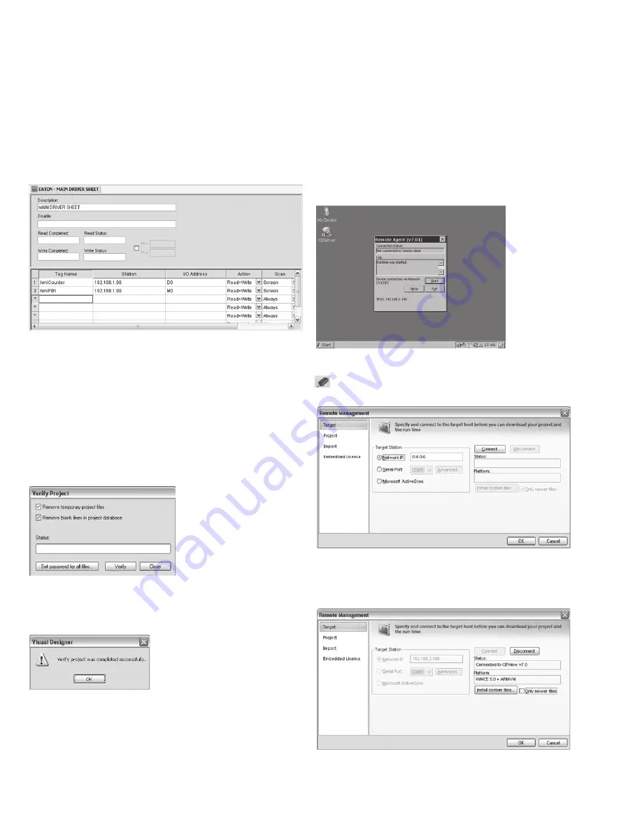
For this project you can copy the tags from the Application Data 

database and paste them into the Main Driver Sheet. Then add the 

station ID which in this example is the IP address of the ELC using 

the default port number 502. Then assign the I/O addresses for each 

tag and change the Scan to Screen as shown below. When finished 

right click on the tab of the worksheet and Save then Close.

3.5.11 Verifying the Application and Creating the  


Runtime Web Pages

Once the project is saved and ready to download to the XV unit, two 

more steps are necessary. The first step is to Verify the application. 

When you save a screen or worksheet, Visual Designer includes 

a pointer to the current database version. When you execute the 

application, Visual Designer compares the screen or worksheet data-

base to the current application database and if there is a mismatch, 

Visual Designer recompiles the expressions. To avoid doing these 

tasks during runtime, we recommend running the 

Verify

 tool before 

downloading and/or finishing an application. To do this select 

Verify


from the Ribbon’s Home tab Tools section. The following dialog will 

be displayed. 

Click on the check-box’s to Remove temporary project files and 

Remove blank lines in project database. This saves disk space and 

cleans up the application prior to downloading. Then click on “Verify”. 

When verify is complete the following dialog will be displayed.

Click “OK” then “Close” on the Verify Project dialog.
Next, to create the Runtime web pages which can be viewed from 

a thin client browser, such as Internet Explorer, over an Ethernet 

network select the 

File > Publish > Save All As HTML

. Once it is 

finished creating the web pages you are ready to connect to the XV 

unit and load the runtime and application files.

3.5.12 Connecting to the XV Unit with Ethernet

There are many ways to connect the development PC to the XV unit 

over Ethernet using a switch, a router, or a cross-over patch cable. 

Refer to chapter 2 of this document to review setting up IP address-

es on both the development PC and XV unit which will enable 

Ethernet communications. On the XV unit the Remote Agent must 

be running. It is set to load at boot up by default, however if it was 

closed you must re-launch it before proceeding. To re-launch it with-

out rebooting the XV unit you can double-click on the 

CEServer

 icon 

on the XV’s desktop display. The Remote Agent window will display 

as shown in the figure below. With the Remote Agent window open 

you can connect to the XV from your PC over Ethernet.

In the Visual Designer editor on the development PC click on  

Connect

 icon in the 

Remote Management

 section of the Home 

tab of the Ribbon. The Remote Management dialog will open  

as shown below.

In the “Target” tab click on the 

Network IP:

 radio button and type in 

the IP address of the XV unit then click on “Connect”. If the Ethernet 

connection is set up correctly the following changes in the dialog 

box will appear.

The Status field will indicate that it is connected and the Platform 

field will indicate the Windows CE Version and the processor type of 

the XV unit.

Summary of Contents for XV-102 Series

Page 1: ...fining Tag Parameters 7 3 4 9 Accessing tag parameters during development 7 3 4 10 Accessing tag fields during runtime 8 3 4 11 Add a tag to your Project 8 3 5 Application Screens 8 3 5 1 Creating a S...

Page 2: ...boot If the device does not boot up and or if an error message appears while starting booting the device see Chapter Troubleshooting and fault rectification manual Operating Instructions XV102 152 1 T...

Page 3: ...does not reply and instead returns Request timed out then contact your network administrator for troubleshooting assistance Further information Hardware manual XV 102 152 system 1 2 Further informatio...

Page 4: ...screen you have the option of defining the resolu tion of an individual Screen If you are creating a Screen Group for a Multiple Document Interface MDI interface i e a collection of smaller Screens t...

Page 5: ...g False or True Integer Four bytes Signed integer number positive negative or zero Equivalent to the C type signed long integer with a range of 2147483647 to 2147483647 Real Floating point eight bytes...

Page 6: ...the same data type have the same name and use an index to uniquely identify a tag that is an element member of the array The use of array tags can simplify the method used to access multiple data item...

Page 7: ...curs These values can be changed during runtime Quality Indicates whether an improper evaluation occurred e g divide by 0 or if there was a bad read from a communication driver e g read or write error...

Page 8: ...m or Trend Worksheet those values will be written into the fields shown here 3 4 10 Accessing tag fields during runtime Accessing Tag Fields Parameters during runtime is straightforward and is done th...

Page 9: ...r Save As when the Screen has not been previously been saved or if you select Save As with an existing Screen All screen files are automatically saved in the Screen subfolder in the Note N application...

Page 10: ...appear Text icon Text Data Link icon You may modify the properties for alignment colors fonts and even the text caption from this property dialog To add the Text Data Link property to this object clic...

Page 11: ...n as shown below and hit OK Make sure to select copy the same hmiPB1 tag in the Indicator property Note that properties which have no ellipsis button to open the Object Finder dialog can still open th...

Page 12: ...s properties that have been added you can click on the property you want to remove with the object selected with or without the dialog displayed and it will toggle the properties off With the Button o...

Page 13: ...ver you want to add click on the driver and then click the Select but ton Then click OK For purposes of this manual we will use the Eaton protocol labelled MODBUS EATON Protocol RTU ASCII CE v1 1 This...

Page 14: ...pace and cleans up the application prior to downloading Then click on Verify When verify is complete the following dialog will be displayed Click OK then Close on the Verify Project dialog Next to cre...

Page 15: ...om internal flash or from the SD card Operation from the SD card The OS that is stored on the SD card is loaded The runtime for Visual Designer and PLC are started from the SD card The Visual Designer...

Page 16: ...e stored in this directory To perform a version change of the operating system the operat ing system image file XV102 BIN must be copied to the directory InternalStorage OS on the XV After this the ch...

Reviews: