11
15kV Class Padmount VisoVac™
instruction manual
MN024004EN April 2021
Sequence of operations – V3 Style Switchgear
Source way operation example
V3 style padmount switchgear comes with vacuum interruption, a visible isolation switch and visible grounding position. VFI
ways and switch ways can only be opened and closed. Electrical interconnections vary depending on the application.
ote:
N
The switchgear can be loop fed, single source fed, or multi-source fed. Users should become familiar with their
application, operating procedures and schematics provided with the equipment before switching.
The following sequence of operations shows the energized and de-energized state of the gear as each operation is
completed. Note the example Model 9-V3 assumes switchgear is fed from a single source. Source way (SW-1) shown only
for clarity. All other ways (VFI-1+) on the gear are considered VFI load ways and are not shown. The example assumes no
load side sources.
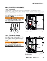
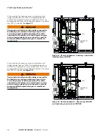
In this position, the vacuum interrupter and the visible
isolation rods are CLOSED. The grounding position is OPEN
and the isolation rod is energized. This example assumes all
ways are energized. See
Figure 24
.
LOAD BUS
SW-1
Source
VFI-1
VFI-2
VFI-3
Loads
Figure 23 . MODEL 9-V3 Single Line Diagram
Isolation Rod
CLOSED
Ground
ROD
OPEN
Load Bus
Source
SW-1
CLOSED
Figure 24 . V3 style padmount – Source Way SW-1
CLOSED
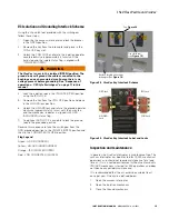
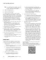
In this position, the vacuum interrupter is OPEN and the
visible isolation rods are CLOSED. The grounding position
is OPEN and the isolation rod is energized only up to the
vacuum bottle contact. This example assumes all load ways
are de-energized since the source way breaker was opened
and the load bus is now de-energized. See
Figure 25
.
WARNING
The cables connected to all bushings, any control power
sources or stored energy devices such as capacitors
must be de-energized/discharged before gear is
considered de-energized .
Isolation Rod
CLOSED
Ground
ROD
OPEN
Source
SW-1
OPEN
Load Bus
Figure 25 . V3 style padmount – Source Way SW-1 OPEN


