Eaton VICKERS DG3V-10 A Series Overhaul Manual Download Page 9

9

A. Type ‘4’ spool allows oil to circulate freely from port 
(P) to port (T) in the center position. Ports (A) and (B) are
blocked to the workload.

T

A

P

B

A B

P T

Closed Crossover, Pressure to ‘‘T’’

with ‘‘A’’ & ‘‘B’’ Blocked

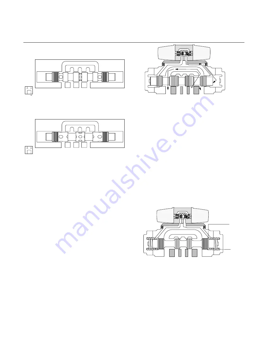
B. Type ‘8’ spool is designed similar to type ‘4’ spool. 
Ports (P) and (T) are connected in the center position. 
However, ports (A) and (B) are momentarily open during 
spool crossover.

T

A

P

B

A B

P T

Tandem, Open Crossover, Pressure to ‘‘T’’

with ‘‘A’’ & ‘‘B’’ Blocked

C. Methods of Spool Control, Main Stage

1. Remote Pilot Source: Main stage valves are available
for use with a remote source. This means that the valve is
shifted from a remote pressure source by other valves in
the logic circuit.

2. Integral Pilot Valve: The integral pilot type two stage valve
is a very common valve used in the field today. Two stage
valves allow large volumes of fluid to be switched to and from
an actuator with minimum power required for control.
Reference figures 3 through 7 shown in the following section.

D. Main Stage Spool Position

Main stage spools are positioned within the valve by special
arrangements. The four basic main stage positioning
arrangements are: no spring-floating, spring centered, spring
offset and pressure centered.

The following paragraphs (1 through 4) describe these
arrangements. A fifth function can be obtained by the use of a
detent pilot valve. This function is described in paragraph five.

1. No Spring-Floating: When centering springs are omitted
from the main stage spool, the spool is said to be floating. If
control pressure is removed, a floating spool can move from
its last position under the influence of gravity or tank line
pressure. This must be considered during the design of the
system. Units with floating type spools have the model code
letter omitted. Figure 3 illustrates floating spool positioning in
a two-stage valve.

Figure 3. No Springs, Floating Model

Solenoid ‘‘A’’ is energized and shifts pilot spool to the
right. This opens pressure to pilot port ‘‘A’’ and the main
stage spool.

When solenoid ‘‘A’’ is energized, the main stage spool
will shift left. Flow from P

³

A and B

³

T is obtained.

Main stage spool will stay in this position until solenoid
‘‘B’’ is energized, but may float to other positions with
both solenoids de-energized.

1.

2.

3.

A

B

T

A

P

B

T

P

B

A

2. Spring Centered: A spring and washer arrangement is
used on both ends of the main stage spool in the spring
centered configuration. If control pressure is removed from a
spring centered spool, the valve will go to the center position
due to spring force. Two configurations of a two-stage spring
centered valve can be obtained, a type ‘B’ and a type ‘C’. If
one solenoid is used on a spring centered pilot valve, the
model code is identified with the letter ‘B’. When two
solenoids are used, the model code is identified with the
letter ‘C’. Figure 4 illustrates spool positioning of a two-stage
spring centered ‘C’ model.

Figure 4. Spring Centered ‘‘C’’ Model

Solenoids are de-energized. Pilot spool is in center
position due to spring force.

Main stage springs and washers keep main stage
spool at center position. Flow is A & B

³

T with 

³

P

blocked.  
When solenoid ‘‘A’’ is energized, the pilot spool will
shift to the right, causing the main stage spool to
shift left. Flow would then be P

³

A and B

³

T.

1.

2.

Main
Stage
Spring

Main
Stage
Washer

T

A

P

B

T

A

B

P

B

A

Summary of Contents for VICKERS DG3V-10 A Series

Page 1: ...5007 01 EN 1099 M DG3V 10 DG5V 10 Solenoid Pilot Operated Overhaul Manual VICKERS Directional Control Valves...

Page 2: ...peration 7 Section IV Pilot Valve Section 13 Section V Internal Valve Functions 15 Section VI Installation 16 Section VII Service Inspection Maintenance 18 Section VIII Overhaul 19 DG5V 8 S H C 10 25...

Page 3: ...contained in this manual The parts and installation drawings listed in Table 1 are available from any Vickers Distributor C Model Codes Variations within each basic model series are covered in the mod...

Page 4: ...psi See spool spring combinations below Left Hand Build L A Models only omit if not required Fast Response X Not available with CETOP 3 pilots or pressure centered D and DB models Spool Control Modif...

Page 5: ...els 2 7 If both are required available on A B C N models 2 8 If both are required available on AL B C N D models CAUTION Stroke adjust pilot pressure models are rated to a maximum of 210 bar 3000 psi...

Page 6: ...ports are open or closed See Figure 1 Oil flow is directed from one port to another within the body and out of a port to the work C Two Stage Directional Valve Construction Two stage directional valv...

Page 7: ...ked and the cylinder is held in a definite position In some circuits flow from the tank port is piped into the pressure port of another valve This allows the same source of power to operate two differ...

Page 8: ...the center position A B P T Closed Center Bleed A B T A P B F Type 52 spool A B P T Closed Center Regen by Solenoid A T A P B G Type 521 spool A B P T Closed Center Regen by Solenoid B T A P B H Type...

Page 9: ...ol can move from its last position under the influence of gravity or tank line pressure This must be considered during the design of the system Units with floating type spools have the model code lett...

Page 10: ...to the sleeve and piston areas on the left side but the sleeve is bottomed against the valve body at this time Only the piston area applies force to the left end of the spool Since the spool land are...

Page 11: ...t To limit the spool travel loosen the jam nut and turn adjusting screw clockwise Figure 8 Stroke Adjuster Feature 2 7 5 1 3 4 6 Main Stage Spool Part No Part Name 1 2 3 4 Cover Spring O Ring Back up...

Page 12: ...Dowel Pin Figure 10 Reducer Module Table 2 Shift Response Times w CETOP 3 Pilot Fast Response option not available Valve Type Condition Pilot Pressure 10 bar 150 psi Pilot Pressure 100 bar 1500 psi P...

Page 13: ...l position 3 Detents A detent mechanism is installed on one or both ends of the pilot valve spool Detent valve solenoids can be momentarily energized to the correct position and then power may be remo...

Page 14: ...Solenoids DG4S4 01 pilot valves are usually equipped with air gap solenoids Air gap solenoids are isolated from system fluid and can be removed and replaced without disturbing the system A push pin a...

Page 15: ...a D Brad Harrison Connectors Brad Harrison connectors thread into the 1 2 NPTF opening in the wiring housing of a DG4V 3 or a DG4S4 01 directional valve PA3 A prefix of PA3 in the model code indicates...

Page 16: ...CAN overcome pilot pressure Drain connection Y is used for externally drained models Pressure centered D models use two drain connections Y and W All external drain connections MUST be piped directly...

Page 17: ...he necessary fittings and connections required for proper installation 3 The number of bends in tubing should be kept to a minimum to prevent excessive turbulence and friction of fluid flow Tubing mus...

Page 18: ...ntenance E Replacement Parts Reliable operation throughout the specified operating range is assured only if genuine Vickers parts are used Sophisticated design processes and material are used in the m...

Page 19: ...Slight variations may be noted on your model depending on the type of accessories and unit design Figure 15 may be used for all models except pressure centered D models regardless of the design Refer...

Page 20: ...emove four screws 3 and crossover plate from main stage body 6 3 Remove and discard two O rings 5 from crossover plate Note The following section pertains to main stage disassembly If your unit does n...

Page 21: ...18 and O ring 19 from core tube S A 20 Discard O Ring 19 6 Remove pilot spool 21 from body 5 7 Remove plugs 24 and 22 and O Ring 23 from body 5 Discard O Ring 23 8 Secure the body and remove plugs 25...

Page 22: ...voltage rating of the coil Refer to Table 8 This test is superficial but a more rigorous test requires special equipment If the coil seems to be burned or extreme heat is encountered during operation...

Page 23: ...Make sure the spool moves freely inside the body bore and is oriented properly See parts drawing 7 Install piston 12 sleeve 11 and spring 10 into cover 8 8 Install O ring 9 in cover and install cover...

Page 24: ...stop 16 spring 17 and push pin 18 on spool 21 4 Install O ring 19 on core tube S A 20 and install core tube S A into body 5 5 Install O ring 9 on core tube S A 20 6 Install gasket 14 and coil 10 on bo...

Page 25: ...at 1 3 Pilot Choke 1 18 Poppet 1 4 Reducer 1 19 Spring 1 5 Body 1 20 Sleeve 1 6 O Ring 9 21 Plug 4 7 Screw 4 22 O Ring 11 8 Adapter Plate 1 23 Plug 10 9 Plug 1 24 O Ring 2 10 Screw 8 25 O Ring 4 11 Co...

Page 26: ...5 O Ring 1 2 Name Plate 1 16 Screw 4 3 Screw 4 17 Cover 1 4 Cover Plate 1 18 O Ring 1 5 O Ring 2 19 Spring 1 6 Body 1 20 Washer 1 7 Screw 4 21 O Ring 2 8 Cover 1 22 O Ring 3 9 O Ring 1 23 Plug 13 10 S...

Page 27: ...Nameplate 1 15 O Ring 2 3 Cover 1 16 O Ring 1 4 Gasket 1 17 Push Pin 1 5 Terminal Box 1 18 Spring 1 6 Gasket 1 19 Washer DC models 2 7 Screw 2 20 Washer AC models 2 8 Strap 1 21 Core Tube S A 1 9 Scr...

Page 28: ...1 22 Plug 1 8 Knob 2 23 O Ring 1 9 O Ring 2 24 Plug 1 10 Coil Type A 2 25 Plug 1 11 DIN Coil 2 26 O Ring 1 12 Plug 2 27 Plug 1 13 DIN Receptacle 2 28 O Ring 1 14 Gasket 2 29 O Ring 5 15 Washer 2 Figu...

Reviews: