background image

27

UPS 20-40 kVA, 230/400 V 50/60 Hz output  

User’s Guide

1025358 
Revision D

The UPS supports two serial communication devices according to the table below.

Independent

Multiplexed

Configuration

XSlot-1

Xslot-2

Std. RS-232 port

Default #1

Any XSlot Module

Any XSlot Module

Not in use

Default #2

Any XSlot Module

Relay Module

Available

Default #3

Any XSlot Module

Not in use

Available

Default #4

Any XSlot Module

Hot Sync card

Available

Table 3  

Typical XSlot configurations for UPS communication.

Web/SNMP Module (optional)

The module supports HTTP and SNMP compliant remote monitoring and shutdown for 
the protected computer systems. It can be connected to a twisted-pair Ethernet network 
(10/100BaseT) using an RJ45 connector. 

The Web/SNMP module has a build-in switching hub that allows three (3) additional network 
devices to be connected to the network without the requirement of additional network drops. 
In addition, an Environmental Monitoring Probe (EMP) can be requested from the UPS 
manufacturer to obtain humidity, temperature and two relay inputs. It is connected to the 
communication port of the Web/SNMP module as option.

Figure 13  

ConnectUPS-X SNMP/Web Module and Environmental Monitoring Probe (EMP).

AS/400 Relay Module (optional)

The Relay Module provides potential free relay interface for AS/400 connected computers and 
industrial applications. The relay interface supports both 15-pin D-sub connector and terminal 
block connections up to four (4) potential free relays.

The relay contacts are rated for 1 A, 30 Vac or 200 mA, 60 Vdc, and they have a galvanic 
isolation from the other circuits of the UPS unit.

Summary of Contents for UPS 20

Page 1: ...User s Guide UPS 20 40 kVA 230 400 V 50 60 Hz output 3 phase input output...

Page 2: ...t of the publisher and may not be reproduced even extracts unless permission granted Every care has been taken to ensure the accuracy of the information contained in this manual but no liability can b...

Page 3: ...ation 12 5 Cabinet installation 13 Maintenance bypass switch 15 External battery cabinet option 15 Battery racks 15 6 Electrical installation 16 Power cables and protective fuses 17 Wiring procedure 1...

Page 4: ...36 Turn UPS from maintenance bypass to normal mode 37 10 Parallel systems 39 Overview 39 SPM cabinets 40 Notice 40 Aux MBS contacts 45 XSlot Hot Sync card installing and wiring 46 Start up and operati...

Page 5: ...to open battery breaker Always ensure by measuring with a multi meter that no dangerous voltages are present Audience The intended audiences of this manual are people who plan the installation install...

Page 6: ...y plates and the MBS locking plate Failure to recognise the electrical hazards could prove fatal Environment The UPS must be installed according to the recommendations in this manual Under no circumst...

Page 7: ...al utility power Working with a building s electrical system the UPS system supplies clean consistent power that sensitive electronic equipment requires for reliable operation During brownouts blackou...

Page 8: ...rough battery when it is discharged or charged There is very little that can be done for discharging because it depends on number of power outages in utility line The ABM is very valuable feature sinc...

Page 9: ...nditioned power at all times Its unique digital design eliminates the system level single point of failure inherent in traditional parallel UPS modules and exponentially increases the reliability of t...

Page 10: ...coming later Residual voltage warning stickers Software Suite CD ROM format English language RS 232 serial cable for the Software Suite Delivery documents Unpacking and visual inspection Check that th...

Page 11: ...Check the information on the type designation label of the equipment to verify that the unit is of the correct type The type designation label includes ratings a CE marking a type code a part number...

Page 12: ...o achieve a long life of the UPS and batteries The cooling air entering the UPS must not exceed 40 C Avoid high ambient temperature moisture and humidity The floor material should be non flammable and...

Page 13: ...attery cabinets that should be installed next to the UPS cabinet Figure 4 UPS and external battery cabinets Note UPS cabinets can fall over if the shipping brackets are not used Both rear and front sh...

Page 14: ...on D Figure 5 Powerware 9355 20 30 kVA and 40 kVA layout 1 Graphical LCD 2 XSlot 1 3 XSlot 2 4 Fans 5 Input rectifier breaker 20 30 kVA switch 40 kVA 6 Battery start button 7 Battery breaker 8 13 Conn...

Page 15: ...e type plate of the UPS and external battery cabinets are the same The cables are delivered with the external battery cabinet Warning The UPS contains high DC voltages A qualified person must do the c...

Page 16: ...PS and extra battery cabinet must be carried out by a qualified service personnel such as a licensed service engineer from the manufacturer or from an agent authorised by the manufacturer Warning Phys...

Page 17: ...ch other Standards SFS 6000 5 52 2002 and IEC 60364 5 52 2001 08 Electrical installations of buildings with normal 1 7 x Neutral conductor rating for IT loads are used as a sizing guide For any other...

Page 18: ...oper terminals 4 Connect the conductors of the load cable to the proper terminals 5 Connect the conductors of an external battery cabinet cable to the external battery and PE terminals Check for the c...

Page 19: ...19 UPS 20 40 kVA 230 400 V 50 60 Hz output User s Guide 1025358 Revision D Figure 7 Wiring diagram of UPS N model with integral MBS...

Page 20: ...20 UPS 20 40 kVA 230 400 V 50 60 Hz output User s Guide 1025358 Revision D Figure 8 Wiring diagram of UPS N model...

Page 21: ...d remove fuses from upper part of the cabinet To be on the safe side measure the voltage accross the terminals to be 0 zero Warning Turn F1 battery breaker from the UPS unit to OFF position and measur...

Page 22: ...nication cables It is recommended that the control cables and power cables be installed on separate trays Where control cables will cross power cables make sure they are arranged at an angle as near t...

Page 23: ...ification of the interface port pins LanSafe software LanSafe software shuts down computers and whole networks in case of an extended power failure It provides basic monitoring data logging notificati...

Page 24: ...ty if one is using a semiconductor switch type A relay or other maintenance control is a preferred method Emergency Power Off EPO This input is used to shut down the UPS from a distance This feature c...

Page 25: ...relay outputs Warning The relay contacts must not be directly connected to mains related circuits Reinforced insulation to the mains is required Programmable signal inputs The UPS incorporates two pro...

Page 26: ...ated separately or at the same time with other building alarms i Not in use default j Shutdown If active the UPS will shutdown immediately k Delayed Shutdown If active the UPS will shutdown after user...

Page 27: ...RJ45 connector The Web SNMP module has a build in switching hub that allows three 3 additional network devices to be connected to the network without the requirement of additional network drops In ad...

Page 28: ...agement software can exchange data with the UPS The software polls the UPS for detailed information on the status of the power environment If a power emergency occurs the software initiates the saving...

Page 29: ...erences in the menu structure between single and parallel mode Parallel Mode Single Mode Main Menu Submenu Menu functions I x x UPS STATUS UPS off System normal UPS supporting load UPS on battery UPS...

Page 30: ...led Disabled Disabled Communication speed 1200 2400 9600 19200 19200 bps Std relay output function UPS ON OK Custom Battery low System on bypass System on battery UPS ON OK Signal input 1 2 function E...

Page 31: ...re turning the output on Disabled Set delay step 1 sec 0 sec Output off automatic delay time on battery after which output is turned off Disabled Set delay step 1 sec Disabled User preferences Operati...

Page 32: ...hat is needed to be configured ALARM 1 is fixed relay output X57 4 Select empty to clear old settings 5 Select custom and activate needed alarms with the button on the right 6 After the selection pres...

Page 33: ...the normal start ups In battery start up battery breaker need to be closed and a green battery start button on the left hand side of the battery breaker pressed till display lits up Start up after EPO...

Page 34: ...detected to be faulty Batteries should be replaced and you need to contact the local office or representative of the UPS manufacturer Battery low The UPS is operating in stored energy mode It will shu...

Page 35: ...batteries may explode Do not open or mutilate batteries Released electrolyte is harmful to the skin and eyes It may be toxic Cooling fan The cooling fan lifespan of the UPS unit is about 60 000 opera...

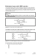
Page 36: ...in the installation part of the manual The MBS is located in the bottom of the UPS near power terminals Note The MBS consist of three switches and failure to understand the correct sequence may drop...

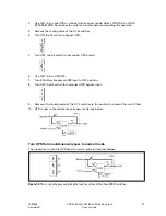
Page 37: ...the S3 switch to disconnect UPS output 6 Use LCD to turn UPS OFF 7 Turn F1 battery breaker and F2 input to OFF position 8 Turn OFF the S2 switch to disconnect UPS bypass input 9 Remount the locking p...

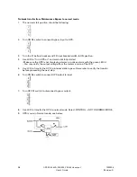
Page 38: ...UPS on and wait until fully started Make sure the UPS is not displaying alarms or notices alarm with the green LED lit You may verify the output voltage from the meters screen of the LCD 5 Use LCD to...

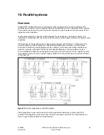
Page 39: ...es of the parallel system share equally the load with Hot Sync technology The parallel outputs can be combined in a System Parallel Module or cabinet It is the system component containing the obligato...

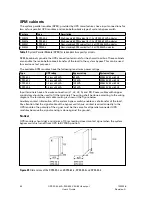
Page 40: ...wing maximum power ratings Type UPS rating Bypass rating System voltage SPM 30 2 1 2 pcs x 30 kVA 60 kVA 400 230 V 50 or 60 Hz SPM 60 2 1 2 pcs x 60 kVA 120 kVA 400 230 V 50 or 60 Hz SPM 30 4 1 4 pcs...

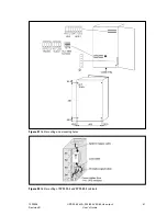
Page 41: ...41 UPS 20 40 kVA 230 400 V 50 60 Hz output User s Guide 1025358 Revision D Figure 21 Cable routing and mounting holes Figure 22 Cable routing of SPM 30 4 and SPM 40 4 cabinets...

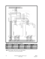
Page 42: ...gram with SPM 30 2 and SPM 60 2 Power Fuse 1 Fuse 2 Cable A B Cable C D 20 kVA 35 A 63 A 10 mm 16 mm 30 kVA 50 A 100 A 10 mm 35 mm 40 kVA 80 A 125 A 25 mm 50 mm 60 kVA 100 A 200 A 35 mm 95 mm Table 10...

Page 43: ...43 UPS 20 40 kVA 230 400 V 50 60 Hz output User s Guide 1025358 Revision D Figure 24 Wiring diagram with SPM 30 4 and SPM 40 4...

Page 44: ...g diagram Note Protection fuses need to be used for load cabling if manufacturers SPM or similar not used Required parallel system wiring length should be in accordance with the following rule as refe...

Page 45: ...sition data connection 1 Remove the door from the UPS 2 Connect the cables in UPS s programmable input terminal X44 or X45 3 Connect communication cables to terminals 1 and 2 for UPS Module 1 and to t...

Page 46: ...26 XSlot Hot Sync card and terminal interface The Hot Sync communication wiring procedure should be done with shielded twisted pair STP as presented in the figure below The maximum length of the cabl...

Page 47: ...2 3 The first and the last UPS modules should have the termination resistor enabled by connecting Pins 1 and 2 with the jumper J7 Figure 28 XSlot Hot Sync card and jumper settings Resistor ON PIN 1 a...

Page 48: ...to ON position 2 UPS will enter a stand by mode and starts to charge batteries with a cooling fan operational Output is without the voltage in the stand by mode 3 Push any key of the control panel to...

Page 49: ...ype and four maintenance switches S1 S2 S3 and S4 for disconnecting the outputs of UPS modules during maintenance or service The maintenance bypass switch has the following positions I or UPS normal p...

Page 50: ...yellow bypass LED is turned off Figure 29 System bypass switch of the optional SPM Shut down procedure While system is running and UPSs are supporting load there are two different ways to perform a s...

Page 51: ...cling the used UPS or batteries Before scrapping UPS or its battery cabinet the battery bank must be removed Local requirements must be followed in battery recycling or discard The removal of batterie...

Page 52: ...52 UPS 20 40 kVA 230 400 V 50 60 Hz output User s Guide 1025358 Revision D 12 Dimensional drawings Figure 30 Dimensions of the UPS cabinet Figure 31 Dimensions of the External Battery Cabinet...

Page 53: ...ration UPS 20 kVA 30 kVA 40 kVA Dimensions Width Depth Height 494 mm 762 mm 1684 mm Weight no battery 36 battery 72 battery 108 battery 144 battery 200 kg 300 kg 400 kg 500 kg 600 kg 217 kg 317 kg 417...

Page 54: ...anagement Nominal voltage 432 Volts Battery qty 36 string Float voltage 2 30 VPC Battery type VRLA 12 Volts Cut off voltage 1 75 VPC Battery charging 6 A user selectable AC output Powerware 9355 20 kV...

Page 55: ...the installation commissioning repair alternation or ambient conditions of the equipment do not fulfil the requirements specified in the documentation delivered with the unit and other relevant docume...

Page 56: ......

Reviews: