3
Instruction Leaflet
IL 29C703D
Effective April 2011
Installation Instructions for Eaton Series C 600 Amp HLD-DC
Circuit Breakers, Circuit Breaker Frame and Molded Case Switch
EATON CORPORATION www.eaton.com
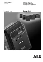
Figure 3. Load Isolated from Power Source. Grounded or
Ungrounded Systems. If System Voltage Exceeds 300 Vdc, then
Ungrounded Systems Only.
Figure 4. Load Connected to Power Source. Grounded or
Ungrounded Systems.
Figure 5. Load Isolated from Power Source. Grounded or
Ungrounded Systems. If System Voltage Exceeds 125 Vdc, then
Ungrounded Systems Only.
Power
Load
Power
Load
Breaker
Breaker
3 Pole
3 Pole
Load Isolated from Power Source.
Grounded or Ungrounded Systems.
If System Voltage Exceeds 300 Vdc.
Then Ungrounded Systems Only.
Fig. 5-2
Breaker
Load
Power
Breaker
Load
Power
2 Pole
2 Pole
Load Connected to Power Source.
Grounded or Ungrounded Systems.
Fig. 5-3
2. Installation
The installation procedure consists of inspecting the circuit breaker
and, as applicable, installing the trip unit, accessories, and terminals;
mounting the circuit breaker; connecting the line and load conduc-
tors; torquing terminals; and attaching terminal shields . Circuit
breaker frames, trip units, accessories, mounting hardware, and
unmounted terminals may be supplied in separate packages . To
install the circuit breaker, perform the following steps .
otee:
N
Internal accessory installation in any type of circuit breaker should be
done before the circuit breaker Is mounted and connected . Refer to individual
accessory instruction leaflets for specific installation instruction on field
installable accessories .
2-1 . Compare nameplate data with existing equipment ratings and
system requirements to make sure that the circuit breaker
is suitable for the intended installation . Prior to mounting,
confirm that the circuit breaker has not been damaged during
transit or initial handling .
2-2 . To install trip unit and any internal accessories, remove
installed cover screws and cover .
otee:
N
The circuit breaker handle must be In the tripped or OFF position to
remove the cover . Instructions for installing the trip unit and accessories are
supplied with the devices .
2-3 . If not already installed, mount the trip unit and accessories (if
required) in circuit breaker frame .
otee:
N
When required to be removed or replaced, stationary interphase barri-
ers can only be installed or removed with the circuit breaker in the tripped or
open position .
2-4 . After the trip unit and any internal accessories are installed,
and with the circuit breaker in the tripped position, make sure
that stationary interphase barriers are properly installed in the
base . Install main cover and secure with supplied pan head
screws . Torque the screws to 20-22 lb .-in (2 .26-2 .49 N .m) .
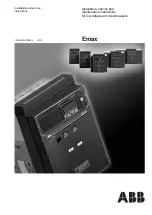
2-5 . If not already installed, mount wire connecting terminals
as shown in
Figure 6
. Secure the terminals to the circuit
breaker using two pan-head slotted screws and lock washers .
Torque to 6 to 8 lb-ft . (8 .14 to 10 .85 N .m) . With the circuit
breaker mounted and before the conductors are installed and
conductor clamping screws inserted, the terminal mounting
screws may be checked for correct torque .
Figure 6. Terminal Installation.
Breaker
Power
Load
2 Pole
Fig. 5-4
Cover
TA603LD
Terminal
Pan-Head
Screws and
Lock Washers
TA602LD
or T602LD
Terminal
Pan-Head Screws
and Lock Washers
(Installed Before
Cable Clamping
Screws)
Circuit
Breaker
Line
Terninal
Cover