3
Technical Data
TD150029EN
Effective November 2020
PXM4/6/8K meter color touchscreen
display quick start guide
EATON www.eaton.com
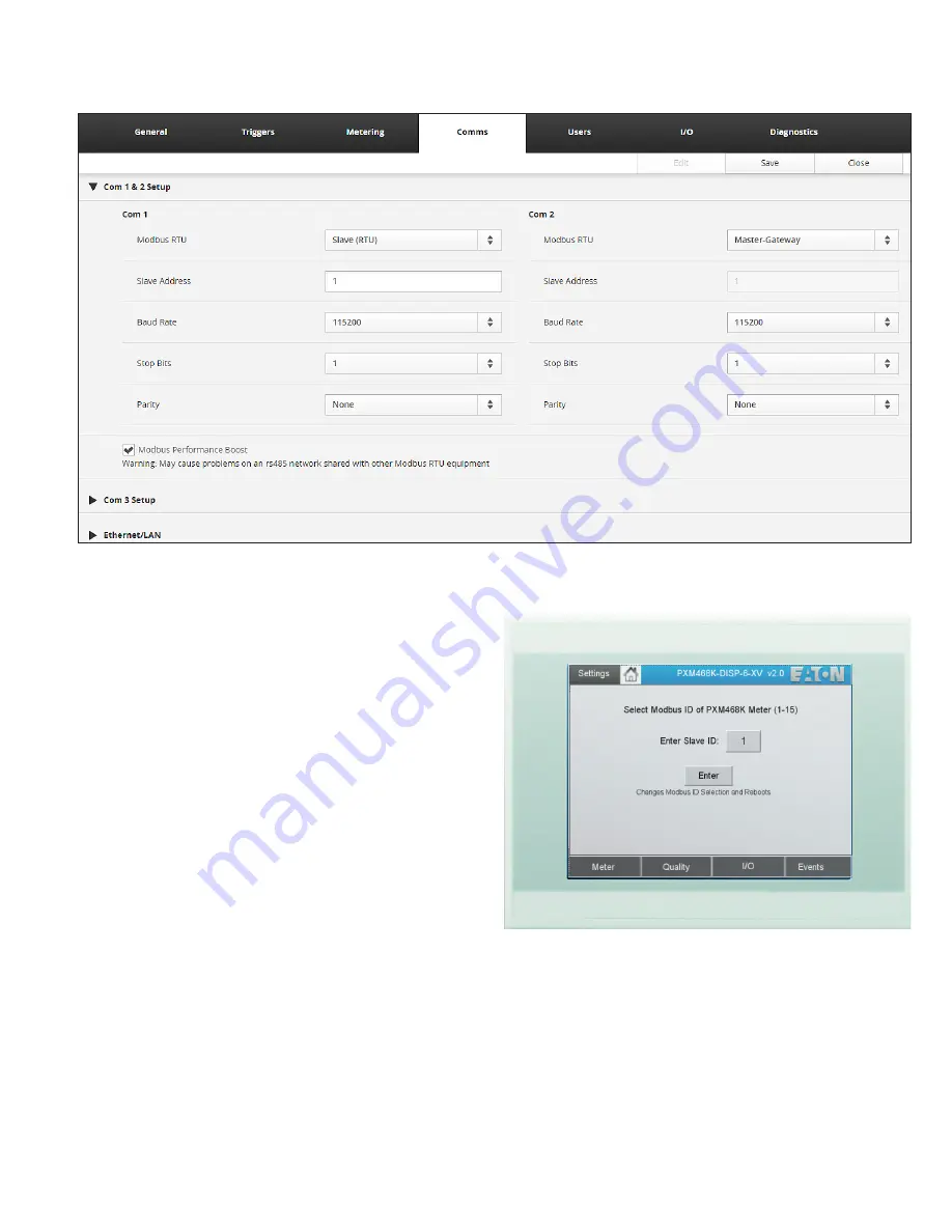
Figure 6. Meter web server configuration screen COM 1 & 2 setup.
Connections
To use the PXM4/6/8K meter color touchscreen display, provide
24 Vdc and connect the power cable between the color touchscreen
display and the PXM4/6/8K meter.
The display’s plug-in terminals provide connections for +24, GND
and common (0).
Included with the PXM4/6/8K meter color touchscreen display is a
data cable to connect the DB9 of the color touchscreen display to
3-terminal COM 1 (RS485) of the PXM4/6/8K meter.
The supplied cables are designed to connect the meter to the
PXM4/6/8K meter color touchscreen display as follows:
•
Data cable: CM3
•
Power cable: CM4
In order to communicate with the display, the meter must be config-
ured as “Slave (RTU).” This can be set using the meter’s web server
configuration page for COM 1 & 2.
For best results, use the default communication settings for the
PXM4/6/8K meter and PXM4/6/8K meter color touchscreen display
(115.2 kbps, 1 start bit, 1 stop bit, no parity).
ote:
N
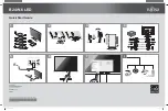
By default, the PXM4/6/8K meter color touchscreen display is pre-
set for a PXM4/6/8K meter Modbus address of “01”. To accommodate a
different Modbus address, the user MUST change the PXM4/6/8K meter
color touchscreen display’s “Modbus ID”. This number MUST match the
rotary switch located on the side of the meter. This setting can be found
under Settings > Meter ID.
Figure 7. Changing the Modbus ID.


