Eaton PRS0100001 User Manual Download Page 25

Operating Instructions

25

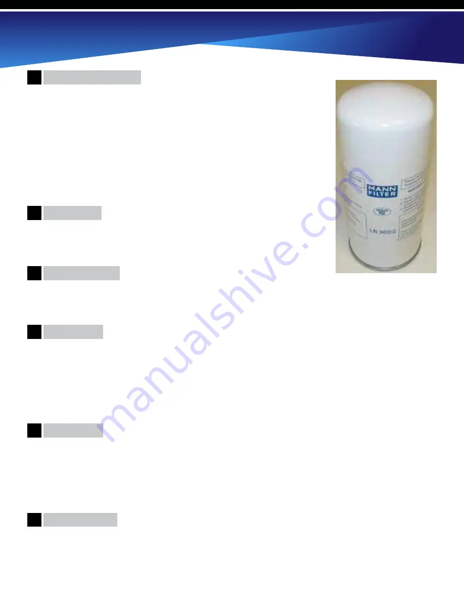
Air/Oil Separator Filter

Safety Valve

Blow Down Valve

Check Valve

After Cooler

Air Storage Tank

11

12

13

14

15

16

During the process of air compression from pump, air and oil are mixed together 
to lubricate, seal and cool compressor rotors. This air and oil is transferred to air/
oil separator tank and then the air/oil separator filter removes oil mist from the 
compressed air. The filter core is made of multiple-layer fine glass fibers. The filter 
reduces the oil particle size and can lower content to less than 3 PPM. During 
normal operation, the air/oil separator filter can be used for about 4000 hours or 
annually, whichever comes first. Refer to the computer controls of the compressor 
to monitor operating time and remember to reset maintenance timer when filter is 
replaced. There is an automatic alarm that can be set to remind operator of service 
times

The ASME certified safety valve on the air/oil separator tank is set to open when 
the pressure exceeds 175 PSI (12.1 bar). NEVER attempt to operate machine 
without ASME safety valve.

The air flows through the check valve then enters the after cooler. The fan on the air cooled after cooler radiator 
draws in ambient air and blows it through the radiator cores to reduce heat in the compressed air and lubricating oil 
exhausted from the rotary screw pump. The heat absorbed in the radiator cores is discharged from the screw cabinet 
because of the cooling fan and generally reduces air temperature by 60°F (15°C). If ambient air temperature exceeds 
112°F (45°C), the system may overheat. It is important to operate the compressor in a well ventilated area for the 
cooling process to be effective.

(optional, not shown)

 The air storage tank can serve as cushion to keep output pressure relatively stable. It can

also reduce operating temperature, remove moisture content, provide cleaner air and reduce the load of the dryer. A 
larger tank also reduces the cycling of the suction valve. As a guideline, for every CFM the compressor produces, a 
minimum of 1.2 gal. of air storage is needed.

The blow down valve is a two-way valve normally open. When the machine is shut down or the compressor is 

unloaded, the vent valve opens and relieves pressure in the air/oil separator tank to ensure the compressor will not be 
started under load.

A minimum pressure check valve is installed after the air oil separator filter. The starting pressure is set at over 43.5 
PSI (3 bar). The functions of the minimum pressure valve are as follows:


a. 

  Actuates oil lubrication of the air end.


b.

   Regulates air flow through the air separator filter to prevent damage to the separator filter element. Air flow  


begins when pressure in the air / oil separator tank reaches 43.5 PSI (3 bar).


c.

   Prevents back flow from the air receiver tank into the air / oil separator tank. This component serves as a  


built-in check valve. No additional check valve is needed for installation.

Summary of Contents for PRS0100001

Page 1: ...Operating Instructions 1...

Page 2: ...and manufactures products for safe operation However operators and maintenance persons are responsible for maintaining safety All safety precautions are included to provide a guideline for minimizing...

Page 3: ...Checks 27 Start Up 28 PowerOutages 28 Storage 29 RestartingProcedure 29 Maintenance 29 Safety Steps 29 30 LubricatingOil 30 ChangingOil 30 OilCapacities 31 Belts 31 SystemPressure 32 SafetyValve 32 Ai...

Page 4: ...1 Oil Capacity 1 1 3gal 3 8 L 1 1 3 gal 3 8 L 1 1 3gal 3 8 L 1 1 3 gal 3 8 L 1 1 2 gal 6 L 1 1 2 gal 6 L Dimensions 26 x34 x43 26 x34 x43 26 x34 x43 34 x24 x43 32 x37 x50 32 x37 x50 Weight lbs 562 562...

Page 5: ...0003 PRS1000003 PRS1250003 PRS1500003 PRS1750003 PRS2000003 Description Three Phase Dual Voltage Three Phase Dual Voltage Three Phase Dual Voltage Three Phase Dual Voltage Three Phase Dual Voltage Thr...

Page 6: ...ng protective shields and barriers electrical protective equipment and personal hearing equipment Breathable Air Pressurized Components Personal Protective Equipment CALIFORNIA PROPOSITION 65 This pro...

Page 7: ...perating practices 1 Carefully inspect all lifting equipment and make sure it is in good condition Rated capacity should exceed compressor weight The lifting hook has a functional safety latch or equi...

Page 8: ...r OSHA Standard 29 CFR 1926 302 b 7 2 Flow limiting valves are listed by pipe size and rated CFM Select appropriate valves accordingly in accordance with the manufacturer s recommendations 3 Do not in...

Page 9: ...te condensate drains on piping system 2 Never use reducers in discharge piping Keep all piping and fittings the same size in the piping system to help prevent pressure drops Never use plastic PVC pipe...

Page 10: ...l be in the compressor The above capacities can be used for guidelines but use the upper arrow fill line on the sight glass See page 7 Over filling causes oil to blowout the inlet valve and through th...

Page 11: ...nstall surge protection device between power supply and compressor electrical cabinet 7 Make sure to install properly sized breakers and fuses 8 The unit must be properly grounded DO NOT connect groun...

Page 12: ...mber and are drained out with the compressed air The PLC is the compressor controller and has a display screen for system information The electric circuitry of the PLC can be divided into two systems...

Page 13: ...elcius or oF Fahrenheit Use the Up Down arrows to change if desired and then press Enter to set the value Now the current flashing gauge pressure setting BAR metric or PSI Am Std shows in display Use...

Page 14: ...hen press enter The current date day of week and time now shows in the display Starting with the flashing date use the Up Down Arrows to change the setting and then press Enter Now the next parameter...

Page 15: ...e Up Down Arrows Press Enter again to confirm the setting Press Down Arrow to see and or change the other pressure settings Once satisfied with all settings press Down Arrow until you are back to the...

Page 16: ...when the low pressure setting is reached the compressor automatically starts again Enter in the 6 Digit Password 6 6 6 6 6 6 by using the Up Arrow to set the digit to 6 then press Enter to move to the...

Page 17: ...sing the Up Down Arrows Press Enter again to confirm the setting See chart on page 17 of PLC manual Once satisfied with all settings press Down Arrow until you are back to the Main Screen Press the tw...

Page 18: ...0 using the Up Down Arrows Then using the Enter button change NO to YES then press Enter and hours are reset Arrow down to 6 OIL FILTER HOURS and press Enter CHANGE AIR FILTER shows in the display and...

Page 19: ...ow and CHANGE OIL FILTER shows in the display but the first Line is C This is the screen for the oil life Press Enter Press Down Arrow and CHECK COMPRESSOR shows in the display Check belt condition an...

Page 20: ...move over to NO and use the Up Arrow to change it to YES then hit Enter and it resets the hours After resetting the Bearing Lubricant timer you can return to the Main Screen by Pressing the Down Arro...

Page 21: ...ons but if the current spikes the overload protection causes the motor s to stop If this happens the motors must be reset manually If motor overload protection is caused by any other reason contact Ea...

Page 22: ...electrical shock could result A Using lock key remove electrical panel from unit B Locate BLUE reset button on relay attached to K1 contactor Example of relay on larger units C Once motor has cooled p...

Page 23: ...ods are available so appropriate features can be selected for different air demands It is important to monitor air demand since it takes 15 more power to operate compressor for every 10 PSI of pressur...

Page 24: ...el pressure vessel used to store lubricating oil and to separate the compressed air and the lubricating oil An oil sight gauge is installed on one end of the air oil separator tank Make sure oil level...

Page 25: ...orbed in the radiator cores is discharged from the screw cabinet because of the cooling fan and generally reduces air temperature by 60 F 15 C If ambient air temperature exceeds 112 F 45 C the system...

Page 26: ...nt or other combustible substances 8 Shut off compressor and allow it to cool before checking or adding lubricant or when refilling air line anti icer systems with antifreeze compound Keep sparks flam...

Page 27: ...of clean water for 15 minutes then contact eye doctor immediately Never store antifreeze compound in confined areas 1 Make sure compressor is properly grounded and verify voltage is correct especiall...

Page 28: ...rvice for assistance 4 Press ON button to begin operation After unit starts a time delay of approximately 5 seconds occurs and a LOADING message displays on PLC screen This means the pump is operating...

Page 29: ...ndensed water in the oil air separator tank and the oil cooler 2 3 days later d Move machine to a clean dry place 1 Remove any wrappings from system components 2 Ensure electric motor is properly insu...

Page 30: ...od condition Replace any wiring that has cracked cut or otherwise damaged insulation Replace terminals that are worn discolored or corroded Keep all terminals and pressure connectors clean and tight 6...

Page 31: ...n the sight glass See page 7 Over filling causes oil to blowout the inlet valve and through the air filter also oil could push past the separation system resulting in oil in the air lines Oil Capaciti...

Page 32: ...ure may be very hot Use caution when changing filter WARNING 1 Relieve all air pressure from air oil separator tank then wait approximately 5 10 minutes before replacing filter 2 Replace air oil separ...

Page 33: ...air filter Replace oil filter 2000 hrs 6 months Change oil replace oil filter Blow out radiator Grease electric motor bearings Check tighten all electrical connections terminals Check belt tension In...

Page 34: ...all electrical connections are secure once power is restored press Enter button on controls 2 Replace fuse s as needed 3 Check for correct voltage and make sure all fuses are functioning 4 Check faul...

Page 35: ...solenoid valve 4 Defective blow down valve 1 Decrease air consumption or increase number of compressors in system 2 Clean or replace air filter 3 Disassemble and clean suction valve Apply lubricating...

Page 36: ...t blockage Increase area ventilation 5 Clean cooler 6 Replace temperature sensor 7 Replace Thermo valve 8 Replace cooling fan 1 Clear blockage clean orifice 2 Change air oil filter 3 Drain and change...

Page 37: ...ect clean 4 Install after cooler 5 Slope drain line away from trap Install drip leg 6 Contact Eaton Compressor 1 Adjust belt tension or replace belts 2 Replace bearing Contact Eaton Compressor 3 Insta...

Page 38: ...ion or replace belts 5 Remove shipping brackets 1 Adjusted belt tension 2 Align sheaves 3 Replace belts 4 Use ONLY OEM parts 1 Replace fuse or reset breaker 2 Replace E Stop button 1 Remove check valv...

Page 39: ...Operating Instructions 39...

Page 40: ...Eaton Compressor Rotary Screw Compressor 40...

Page 41: ...Operating Instructions 41...

Page 42: ...Eaton Compressor Rotary Screw Compressor 42...

Page 43: ...or any caustic or abrasive matter that may be ingested into the pump or installing the unit in an enclosed area where lack of cooling ventilation is present such as in boiler or equipment rooms where...

Reviews: