background image

COMMUNICATION FEATURES

Eaton 9910 UPS and EBM Installation Guide (6000 VA Models)  

S

  P-164000007 Rev 1


38

Communication Cards

Communication cards allow the UPS to communicate in a variety of
networking environments and with different types of devices. The
optional card must be purchased separately.

NOTE  

You do not have to shut down the UPS to install an optional communication card.

The Eaton 9910 has an available communication bay for one of the
following communication cards:

S

Network Management Card

. Provides power management software to

control load segments, set the time and date, configure other
settings, and update the UPS firmware.

S

Relay-Serial Card

. Provides two types of interfaces through a DB-9

connector: a dry contact (relay) mode and an RS-232 (serial) mode.

For information about installing, configuring, and using an optional card,
refer to the card's user guide for more information.

NOTE  

To use the Relay-Serial Card with IBM servers, leave the jumpers in the default

position (middle of the card).

Load Segments

Load segments are sets of receptacles that can be controlled by power
management software, providing an orderly shutdown and startup of
your equipment. For example, during a power outage, you can keep key
pieces of equipment running while you turn off other equipment. This
feature allows you to save battery power. See the User's Guide or your
power management software manual for details.

Each UPS has two load segments as shown in “UPS Rear Panels” on
page 18.

Summary of Contents for Powerware 9910 UPS

Page 1: ...Powerware Series Eaton 9910 UPS and EBM Installation Guide for IBM Applications 6000 VA Models...

Page 2: ......

Page 3: ...Powerware Series Eaton 9910 UPS and EBM Installation Guide for IBM Applications 6000 VA Models...

Page 4: ...ity Oy Koskelontie 13 FIN 02920 Espoo Finland Phone 358 9 452 661 Fax 358 9 452 665 68 Eaton and Powerware are registered trademarks of Eaton Corporation or its subsidiaries and affiliates IBM and AIX...

Page 5: ...sidential area is likely to cause harmful interference in which case the user will be required to correct the interference at his own expense ICES 003 This Class A Interference Causing Equipment meets...

Page 6: ...ion such as important operating and maintenance instructions This symbol indicates that you should not discard the UPS or the UPS batteries in the trash This product contains sealed lead acid batterie...

Page 7: ...ernal Battery Connection 21 Connecting the EBM 28 Remote Emergency Power off REPO 29 About REPO 29 Installing REPO 29 Initial Startup 31 4 Shipping the UPS in a Rack 33 Installing the Shipping Bracket...

Page 8: ...TABLE OF CONTENTS Eaton 9910 UPS and EBM Installation Guide 6000 VA Models S P 164000007 Rev 1 ii 7 Service and Support 39 Updating the UPS Firmware 39 Contacting Service 39...

Page 9: ...16 00P S 9003 4025 00P S 730 B0108 00P 9910 E66 UPS 6000 VA 208V S 4U cabinet 208V S Battery 2 1 730 B0104 00P Rail Kit 1 373 52327 00 6000 VA Shipping Bracket 1 74Y8485 744 A1322 00P 9910 E66 and 991...

Page 10: ...41 00 UPS Management Software CD ROM 1 P 164000007 6000 VA UPS and EBM Installation Guide 1 614 03781 00 REACH document 1 730 B0348 00P UPS upper front cover with LCD opening 1 730 B0029 00P UPS lower...

Page 11: ...er 16 420 90804 00 Screws M5 16 round slotted for rack installation Table 8 Network Management Card NMC Base Configuration 74Y8489 Quantity IBM MTM IBM FC IBM PN Eaton PN Description 1 2945 74Y8489 71...

Page 12: ...e and file a claim for shipping damage If you discover damage after acceptance file a claim for concealed damage To file a claim for shipping damage or concealed damage 1 File with the carrier within...

Page 13: ...risk of fire or electric shock install this UPS in a temperature and humidity controlled indoor environment free of conductive contaminants Ambient temperature must not exceed 40 C 104 F Do not opera...

Page 14: ...nadvertently grounded remove the utility source from the ground Contact with any part of a grounded battery can result in electrical shock The likelihood of such shock can be reduced if such grounds a...

Page 15: ...t sous tension m me lorsque l onduleur n est pas connect e une alimentation CA S Pour r duire les risques d incendie et de d charge lectrique installer l onduleur uniquement l int rieur dans un lieu d...

Page 16: ...re par m garde retirez la source secteur de la terre Le contact avec toute pi ce d une batterie mise la masse peut provoquer un choc lectrique La probabilit d un tel choc peut tre r duite si de telles...

Page 17: ...romquelle angeschlossen ist S Um die Brand oder Elektroschockgefahr zu verringern diese USV nur in Geb uden mit kontrollierter Temperatur und Luftfeuchtigkeit installieren in denen keine leitenden Sch...

Page 18: ...st Im Falle der unbeabsichtigten Erdung ist die Netzstromquelle von der Erdung zu entfernen Durch Ber hrung von geerdeten Batterieteilen kann ein elektrischer Schlag verursacht werden Die Wahrscheinli...

Page 19: ...mo que este n o esteja conectado a uma fonte de energia el trica S Para reduzir o risco de inc ndios ou choques el tricos instale a UPS em ambiente interno com temperatura e umidade controladas e livr...

Page 20: ...rrada inadvertidamente remova a fonte utilit ria do aterramento Tocar qualquer parte de uma bateria aterrada pode resultar em choque el trico A possibilidade de choque el trico pode ser reduzida se es...

Page 21: ...SAFETY WARNINGS Eaton 9910 UPS and EBM Installation Guide 6000 VA Models S P 164000007 Rev 1 13 S S 40 90 S 9910 E66 30A 9910 E67 40A S S 3 5 S...

Page 22: ...SAFETY WARNINGS Eaton 9910 UPS and EBM Installation Guide 6000 VA Models S P 164000007 Rev 1 14 S S 1 2 3 4 5 S S S S S S S EBM...

Page 23: ...n una fuente de CA S Para reducir el riesgo de incendio o de choque el ctrico instale este SIE en un lugar cubierto con temperatura y humedad controladas libre de contaminantes conductores La temperat...

Page 24: ...ertidamente quite la fuente de energ a de la tierra El contacto de cualquier parte de una bater a con toma a tierra puede provocar un cortocircuito el ctrico La posibilidad de tal cortocircuito puede...

Page 25: ...omes with your rack cabinet for safety and cabling information NOTE Removing the rack doors and side panels might make installation easier See the rack cabinet documentation for more information S Ver...

Page 26: ...properly wired and grounded electrical outlets S Do not overload the power outlet when you install multiple devices in the rack cabinet UPS Rear Panels NOTE The shaded areas shown in the following fi...

Page 27: ...teps in this section if you are replacing an existing installed EBM with a new EBM If you are installing a new UPS or EBM continue to Rack Installation and UPS Internal Battery Connection on page 21 N...

Page 28: ...BM See the recycling information in the User s Guide for proper disposal 3 Align the EBM power cord with the EBM connector on the UPS Firmly press the power cord into the UPS See Figure 3 NOTE A small...

Page 29: ...internal batteries To install a UPS or EBM in a rack cabinet 1 If your rack has round holes continue to Step 2 Otherwise skip to Step 6 2 Locate the four adapter plates that come in the rail kit 3 Pe...

Page 30: ...inet as shown in Figure 6 Figure 6 Adjusting the Rail Length 7 Select a location in the the rack cabinet for the UPS or EBM 8 Secure each rail to the front of the rack with two M5 16 mm screws Verify...

Page 31: ...shown in Figure 8 Figure 8 Attaching the Rears of the Rails 10 Tighten the rail adjustment screw in the middle of each rail 11 If you are installing a UPS continue to Step 12 If you are installing an...

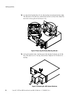
Page 32: ...ket slide the bracket to the left 2 rotate the bracket out 3 then slide the bracket to the right and remove it 4 Figure 9 Removing the Battery Retaining Bracket 13 Using the plastic tab carefully pull...

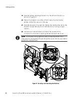
Page 33: ...ure 11 Installing the Cabinet in the Rack 15 Secure the front of the UPS or EBM to the rack cabinet with four M5 16 mm screws as shown in Figure 11 16 If the rack cabinet has conductors for grounding...

Page 34: ...acket to the right 3 Tighten the thumbscrew 4 on the bracket Torque the screw to 0 7 Nm 6 2 lb in if using a torque wrench 22 Connect each internal battery connector 5 and attach the connectors to the...

Page 35: ...over the LCD on the front of the UPS and snap it into place See Figure 13 25 To install the lower front cover press the two side latches toward each other align the cover underneath the upper front c...

Page 36: ...e UPS 1 Verify that the EBM is installed in the rack cabinet directly below the UPS 2 Align the EBM power cord with the EBM connector on the UPS FIrmly press the power cord into the UPS See Figure 14...

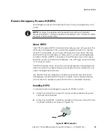
Page 37: ...nt of a room overtemperature condition When a REPO is activated the UPS shuts down the output and all its power converters immediately The UPS logic power remains on to issue an alarm The REPO feature...

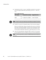
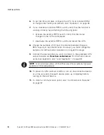
Page 38: ...neously cause UPS input AC power to be removed 4 The REPO contacts are closed by default and cannot be changed The pins must be kept closed to keep the UPS running If the UPS shuts down because the RE...

Page 39: ...isplay is illuminated The Eaton startup screen changes to the UPS status summary screen Standby status is displayed on the front panel of the UPS Figure 17 on page 35 describes the display buttons 4 P...

Page 40: ...s With load the internal batteries charge to 90 capacity in less than 8 hours However you must charge the batteries for 48 hours after installation or long term storage 9 Connect the devices that you...

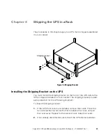
Page 41: ...ipping Bracket on the UPS You must install the shipping bracket on the front of the UPS before the UPS is shipped installed in a rack cabinet The shipping bracket provides extra protection for the UPS...

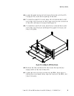
Page 42: ...ion for the UPS during shipment Before using the UPS remove the shipping bracket on the front of the UPS To remove the shipping bracket 1 If the UPS front covers are installed remove the covers Press...

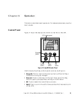
Page 43: ...f the UPS Figure 17 Eaton 9910 Control Panel The front panel has three control buttons and one on off button S Escape X Press to return to the previous menu without running a command or saving any cha...

Page 44: ...attery mode Turning off the UPS To turn off the UPS 1 Prepare the connected devices for shutdown 2 Press and hold the on off button until the long beep ceases approximately 3 seconds The UPS transfers...

Page 45: ...to protect the data before the UPS shutdown occurs You can install the UPS Manager software on a computer running a Microsoft Windows Linux or AIX operating system as either a standalone application...

Page 46: ...S Relay Serial Card Provides two types of interfaces through a DB 9 connector a dry contact relay mode and an RS 232 serial mode For information about installing configuring and using an optional car...

Page 47: ...vice In the United States and Canada call the IBM Service Support Center at 800 IBM SERV 800 426 4968 In Europe the Middle East and Africa EMEA Latin America or Asia Pacific call the IBM office that s...

Page 48: ...SERVICE AND SUPPORT Eaton 9910 UPS and EBM Installation Guide 6000 VA Models S P 164000007 Rev 1 40...

Page 49: ......

Page 50: ...P 1640000071 P 164000007 1...

Reviews: