background image

10

Introduction

Instruction manual—single-phase power conditioners

   IM01002005E   September 2015   Eaton.com

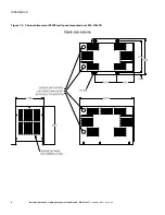
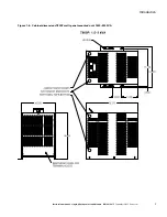
Figure 1-9:  Cabinet dimensions T800F floor-mounted unit, 15,000–25,000 VA

Summary of Contents for Power-Sure 800 Series

Page 1: ...Instruction manual single phase power conditioners Power Sure 800 ...

Page 2: ...ving 1 1 3 Location and storage 1 1 4 Prerequisites to installation 1 1 5 General description 1 1 6 Electrical specifications 2 1 7 Power Sure T800R T800P T800F cabinet dimensions 3 SECTION 2 INSTALLATION 2 0 Scope 11 2 1 Installation notes 11 2 2 Installation of hardwired models 11 2 3 Wiring diagrams 12 2 4 Input volts and amps specifications 500 VA 5 kVA 18 2 5 Input volts and amps specificatio...

Page 3: ... VA T800R 120 Vac input and output 60 Hz 12 2 2 Wiring diagram for 1 2 5 kVA T800R 120 Vac input and output 60 Hz 12 2 3 Wiring diagram for 3 5 kVA T800R 120 Vac input and output 60 Hz 13 2 4 Wiring diagram for 3 5 kVA T800R 208 240 Vac input and 120 Vac output 60 Hz 13 2 5 Wiring diagram for 5 7 5 kVA T800R 208 240 Vac input and 120 208 240 Vac output 60 Hz 14 2 6 Wiring diagram 10 15 kVA T800R m...

Page 4: ...energy and if not installed and used in accordance with the instruction manual may cause harmful interference to radio communications Operation of this equipment in a residential area is likely to cause harmful interference in which case the user will be required to correct the interference at the users own expense Certification standards ANSI IEEET C57 12 91 transformer test code ANSI C62 41 Cate...

Page 5: ...g policies The sole source governing the rights and remedies of any purchaser of this equipment is the relevant Eaton selling policy No warranties express or implied including warranties of fitness for a particular purpose or merchantability or warranties arising from course of dealing or usage of trade are made regarding the information recom mendations and descriptions contained herein In no eve...

Page 6: ..._________________________________ _________________________________________________ _________________________________________________ _________________________________________________ _________________________________________________ _________________________________________________ _________________________________________________ _________________________________________________ ________________...

Page 7: ...e sides of the enclosure Air exhausts are at the rear of the enclosure Therefore it should be installed in a clean dry place with enough clearance to allow a free flow of air Allow at least four inches of space between the unit and the wall or other equipment for portable units Allow enough space for maintenance on all four sides on larger units and unrestricted air exhaust from the fan Never moun...

Page 8: ...hing unity with load power factor as poor as 0 6 Meets FAA G 201e power factor specifications Harmonic attenuation 23 dB for load reflected harmonics Galvanic isolation NEC 250 5d 001pf Surge protection Complies with UL 1449 rating 330 V ANSI IEEE C62 41 Cat B3 Short circuit protection The Power Sure T800R T800P T800F can not be damaged by electrical short in the load Voltage recovery Output volta...

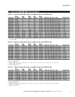
Page 9: ...8 6 x 355 6 x 254 0 52 24 T800P 00750 750 750 Range 1 ac Range 3 d Hardwired Hardwired 9 00 x 14 00 x 10 00 228 6 x 355 6 x 254 0 60 27 T800P 01000 1000 1000 Range 1 ac Range 3 d Hardwired Hardwired 9 00 x 14 00 x 10 00 228 6 x 355 6 x 254 0 82 37 T800P 01500 1500 1500 Range 1 ac Range 3 d Hardwired Hardwired 13 00 x 16 50 x 14 75 330 2 x 419 1 x 374 7 106 48 T800P 02000 2000 2000 Range 1 ac Range...

Page 10: ...E 1 5 1 5 30R 120 30 S 1 1 L5 30R 120 30 F 1 1 6 15R 208 240 15 T 1 1 L6 15R 208 240 15 G 1 2 6 15R 208 240 15 U 1 2 L6 15R 208 240 15 H 1 1 6 20R 208 240 20 V 1 1 L6 20R 208 240 20 I 1 2 6 20R 208 240 20 W 1 1 L6 30R 208 240 30 J 1 5 1 6 30R 208 240 30 X 1 1 L14 20R 120 240 20 K 1 5 1 6 50R 208 240 50 Y 1 1 L14 30R 120 240 30 L 1 1 14 20R 120 240 20 Example T800R 100002B2Y consists of 2 2 5 15R r...

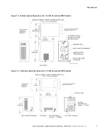
Page 11: ...manual single phase power conditioners IM01002005E September 2015 Eaton com Figure 1 3 Cabinet standard dimensions for 1 3 5 kVA Power Sure T800R models Figure 1 4 Cabinet standard dimensions for 5 15 kVA Power Sure T800R models ...

Page 12: ...6 Introduction Instruction manual single phase power conditioners IM01002005E September 2015 Eaton com Figure 1 5 Cabinet dimensions T800P wall panel mounted unit 500 1000 VA ...

Page 13: ...7 Introduction Instruction manual single phase power conditioners IM01002005E September 2015 Eaton com Figure 1 6 Cabinet dimensions T800P wall panel mounted unit 1500 3000 VA ...

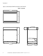
Page 14: ...8 Introduction Instruction manual single phase power conditioners IM01002005E September 2015 Eaton com Figure 1 7 Cabinet dimensions T800P wall panel mounted unit 5000 10 000 VA ...

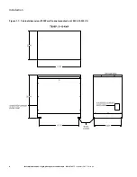
Page 15: ...9 Introduction Instruction manual single phase power conditioners IM01002005E September 2015 Eaton com Figure 1 8 Cabinet dimensions T800F floor mounted unit 5000 10 000 VA ...

Page 16: ...10 Introduction Instruction manual single phase power conditioners IM01002005E September 2015 Eaton com Figure 1 9 Cabinet dimensions T800F floor mounted unit 15 000 25 000 VA ...

Page 17: ...and output field wiring connections are made to the correct terminal blocks as shown for the specific model being installed See Figures 2 5 page 14 2 6 page 15 2 7 page 16 or 2 8 page 17 depending on the model being installed Installation 2 0 Scope This section guides the user through installation requirements circuit wiring diagrams hardwire connections and factory input output configurations for...

Page 18: ...gle phase power conditioners IM01002005E September 2015 Eaton com 2 3 Wiring diagrams Figure 2 1 Wiring diagram for 500 850 VA T800R 120 Vac input and output 60 Hz Figure 2 2 Wiring diagram for 1 2 5 kVA T800R 120 Vac input and output 60 Hz ...

Page 19: ... Vac load currents X1 N or X2 N should not exceed 50 of the unit s rated power 120 Vac Neither duplex receptacle should be loaded more than 14 5 A Figure 2 4 Wiring diagram for 3 5 kVA T800R 208 240 Vac input and 120 Vac output 60 Hz Note 3 5 kVA 120 Vac load currents X1 N or X2 N should not exceed 50 of the unit s rated power 120 Vac Neither duplex receptacle should be loaded more than 14 5 A ...

Page 20: ...14 Installation Instruction manual single phase power conditioners IM01002005E September 2015 Eaton com Figure 2 5 Wiring diagram for 5 7 5 kVA T800R 208 240 Vac input and 120 208 240 Vac output 60 Hz ...

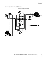
Page 21: ...15 Installation Instruction manual single phase power conditioners IM01002005E September 2015 Eaton com Figure 2 6 Wiring diagram 10 15 kVA T800R models ...

Page 22: ... 2015 Eaton com Figure 2 7 Wiring diagram 500 VA 5 kVA T800P T800F models Terminals 500 2500 VA 8 stud Maximum wire size 10 AWG Recommended torque 15 lb in 3000 VA 10 stud Maximum wire size 6 AWG Recommended torque 20 lb in 5000 VA Wire size range 12 1 0 AWG Recommended torque 45 50 lb in ...

Page 23: ... IM01002005E September 2015 Eaton com Figure 2 8 Wiring diagram 8 25 kVA T800P T800F models Terminals Wire size range 12 1 0 AWG Recommended torque 45 50 lb in Note Full kVA ratings may be used at 120 Vac on secondary windings with exception of 20 kVA and 25 kVA units ...

Page 24: ... 7 A 1 kVA T800P 01000 9 2 A 5 3 A 4 6 A 2 3 A 1 5 kVA T800P 01500 13 7 A 7 9 A 6 8 A 3 4 A 2 kVA T800P 02000 18 3 A 10 5 A 9 2 A 4 6 A 3 kVA T800P 03000 27 5 A 15 8 A 13 7 A 6 9 A 5 kVA T800a 05000 45 8 A 26 4 A 22 9 A 11 4 A a P wall mounted F floor mounted Note Recommended input circuit breaker should be sized 125 of stated input amperage Input Output 120V H1 H2 120V X1 N 208V H1 H3 208V X1 X2 ...

Page 25: ...2 Input volts and amps specifications 8 25 kVA Power rating Model 208 V 240 V 480 V 8 kVA T800 a 08000 42 A 37 A 18 A 10 kVA T800 a 10000 53 A 46 A 23 A 15 kVA T800F 15000 80 A 70 A 34 A 20 kVA T800F 20000 106 A 92 A 46 A 25 kVA T800F 25000 132 A 115 A 57 A a P wall mounted F floor mounted Note Recommended input circuit breaker should be sized 125 of stated input amperage Input Output 208V H1 H2 1...

Page 26: ... three main component types in the Power Sure T800R T800P T800F power conditioners transformer capacitors and cooling fans 1 Transformers The transformer is designed with a considerable safety margin Normally the only malfunction that can take place is a short to the core It can be checked easily with an ohmmeter 2 Capacitors Capacitors can be defective in the open or shorted mode and checked easi...

Page 27: ...____________________________________________ _____________________________________________________ _____________________________________________________ _____________________________________________________ _____________________________________________________ _____________________________________________________ _____________________________________________________ _______________________________...

Page 28: ...ng a world that demands more With over 100 years experience in electrical power management we have the expertise to see beyond today From ground breaking products to turnkey design and engineering services critical industries around the globe count on Eaton We power businesses with reliable efficient and safe electrical power management solutions Combined with our personal service support and bold...

Reviews: