20
Switches, GHG 981,
industrial design up to 250 A, 3 and 6-pole
GB
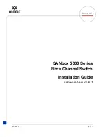
Pipe fixing
Wall,- channel fixing
C
Fastening holes for
10 A 3-pole safety switch
B
Snap-on fixing points for
25A 3-pole safety switch
Snap-on fixing points for 25 A 6-pole
and 40 A 3-pole switches
B
Fig 2 Size 1 Apparatus holder
Fig 3 Size 2 Apparatus holder
Fig 4 Size 3 Apparatus holder
6 Installation
The relevant national regulations and the generally recognized rules of
engineering apply for the installation and operation�
The improper installation and operation of switches may result in
the invalidation of the guarantee.
6�1 Mounting
The switch can be mounted without opening its enclosure (with the
exception of the 10 A safety switch)�
When being mounted directly onto the wall, the switches shall rest evenly
only at the fastening points provided for them�
The chosen screw shall match the fastening hole (see dimensional
drawing) and they shall not damage the hole (e�g� use of a washer)�
The switches 25A, 40A and 80A shall be fixed diagonally with a minimum
of 2 screws�
The switches 100A -250A shall be fixed with a minimum of 4 screws�
If the screws are overtightened, the apparatus may be damaged.
The 10 A, 40 A 6-pole, 80 A, 100 A, 125 A, 160 A, 180 A and 250A
switches are suitable for fastening onto Cooper Crouse-Hinds / CEAG
apparatus holders by means of self-cutting screws (see fig� 2 and 5)�
The 25 A and 40 A 3-pole switches can be snapped on at the catch points
of the apparatus holder (see fig� 3 and 4)�
See the respective mounting instructions�
6�2 Opening the device/Electrical connection
Before opening the apparatus, ensure that it has been isolated
from the voltage supply, or take appropriate protective measures.
Before opening, set the switch to the „ON“ position�
Switching at the shaft of the switch base while the enclosure is
open, is not permitted (in order that the switch can be properly
reclosed).
The electrical connection of the apparatus may only be carried out by
skilled staff.
After dismantling built-in components in order to facililate the
introduction of cables, such components will have to be properly
fitted in again prior to the electrical connection.
The properly bared conductors of cables shall be connected with due
regard to the respective regulations�
To maintain the explosion protection, conductors shall be
connected with special care.
The insulation shall reach up to the terminal. The conductor itself
shall not be damaged.
The minimum and maximum conductor cross sections that can be
connected shall be observed (see technical data).
All screws and/or nuts of the supply terminals, also of those remaining
vacant, shall be tightened down�
The 80 A safety switch can be connected by means of 35 mm² DIN cable
terminals� The 125/180 A safety switch may only be connected by means
of the cable terminals included in our delivery�
The cable lugs should be crimped onto the cable in a workmanlike
manner.
It is to be ensured that the required min. air gaps are kept
(at 690V >12mm).
Pipe fixing
Fig 5 2 x Size 3 apparatus holder
A
Fastening holes for
40 A 6-pole,
80A 3- and 6-pole,
100 A 3-pole,
160 A 3-pole -
(dimension X = 0 mm)
Fastening holes for
125/180 A 3-pole,
250A 3-pole,
100 A 6-pole
(dimension X = 273 mm)