background image

68 

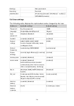
EPO (Emergency Power Off)


EPO on the rear panel of UPS, disconnecting the EPO can cut off the output of 

the UPS. 


Dry in & Dry out   

Dry in is optical coupling input interface, which is connected to an external switch. 

After custom setting the dry contact input function, it can perform operations such 

as power on and power off. 

Dry  out  is relay  output  interface,  which  is  normally  open,  can  be  used  to  indicate 

the  UPS  load  overload,  battery  mode,  battery low  voltage, battery  not connected, 

bypass output and other working conditions. 


Refer to 5.4 to setting Dry in & out details 


Intelligent slot(support hot swap) 

Intelligent slot can be installed with Genepi-IT communication card, Genepi-FA 

Modbus card and Relay-MS dry contact card. If necessary, please contact your 

supplier. 


Summary of Contents for DXRT 10KS31-IN Series

Page 1: ...Eaton DXRT 10KXL31 系列 系列 系列 系列 在线式 UPS ...

Page 2: ...I 2017伊顿 伊顿 伊顿 伊顿 EATON 公司 公司 公司 公司 保留所有权利 保留所有权利 保留所有权利 保留所有权利 本手册内所包含的所有内容属于伊顿所有 未 经许可 不得复制 或摘录 我们已经尽一 切努力确保手册内信息的正确性 但出现错误 或遗漏是难免的 对此我们不负任何责任 并 保留对设计进行修改的权利 ...

Page 3: ...此手册 6 清洁时 请使用干燥的物品进行擦拭 7 若遇火警 请正确使用干粉灭火器进行灭火 勿使用液体灭火器 以免触电 电气安全 电气安全 电气安全 电气安全 1 上电前 请确认已正确接地 并检查所有接线和电池极性的连接正确 2 当UPS需要移动或重新接线时 应将交流输入电源断开 并保证UPS完全关 机 否则输出端仍可能带电 有触电的危险 3 请使用本公司指定的附加装置和附件 4 为了符合EMC的要求 UPS的输出线长度应在10米以内 电池安全 电池安全 电池安全 电池安全 1 电池的寿命随环境温度的升高而缩短 定期更换电池可保证UPS工作正常 并 保证足够的后备时间 2 蓄电池的维护必须由具备蓄电池专业知识的人员来进行 3 更换蓄电池 其类型 型号与数量均应与原电池保持一致 4 蓄电池存在电击危险和短路电流危险 为避免触电伤人事故 在更换电池时 请遵守下列警告 A 请勿佩带手表 戒指或类似...

Page 4: ...电解液含有强酸等危险物质 会对皮肤和眼睛造成伤害 如果不小心接触到电解液 应立即用大量的清水进行清洗 并去医院检查 7 请勿将电池正负极短路 否则会导致电击或着火 使用保养 使用保养 使用保养 使用保养 1 使用环境及保存方法对本产品的使用寿命及可靠性有一定影响 因此 请注意 避免在下列工作环境中使用 A 超出技术指标规定 温度 0 50 相对湿度 0 95 的高 低温和潮 湿场所 B 有振动 易受撞击的场所 C 有金属性粉尘 腐蚀性物质 盐份和可燃性气体的场所 2 如果长时间放置不使用 必须将 UPS 不带电池 存放在干燥的环境中 存 贮温度范围 25 60 UPS 开机之前 必须先让环境温度回升至 0 以上 并维 持 2 小时以上 ...

Page 5: ...安装 8 3 1 拆包检查 8 3 2 配线表 8 3 3 机架式和塔式安装 9 3 4 电池箱和 UPS 主机的组合安装 12 4 连接 14 4 1 市电连接 UPS 15 4 2 电池箱连接 UPS 16 4 3 其他电池箱连接长效机 UPS 17 4 4 MBP 接入 UPS 选配 17 4 5 并机的安装及操作 选配 18 4 6 通讯接口 20 5 操作 22 5 1 控制面板 22 5 2 LCD 描述 24 5 3 LCD 菜单 25 5 4 用户设置 26 5 5 UPS 开机和关机 26 5 6 LCD 操作 27 6 电池维护与保养 35 7 维修保证 36 8 故障排除 37 附录 技术规格 40 ...

Page 6: ...无间断地由电池继续供电 在过载或逆变失败情况下 UPS会转换 到旁路状态 由旁路供电 若过载情况消除 UPS会自动切换到逆变供电状态 本产品支持支持三进单出和单进单出两种输入输出模式 输出功率因数高 达1 0 满足用户更高负载的需求 16 20节电池可调 用户可选择更多的电池 配置方案 充电电流1 12A灵活设置 在线双转换模式效率高达95 更加节 能环保 可灵活地实现塔式与机架式两种安装方式 适用于服务器 存储 网络设备 精密仪器等应用环境 为关键设备提供优质可靠的交流电源 本手册仅适用于 Eaton DXRT 10KXL31 系列 具体型号 尺寸及重量等如下表格 型 号 尺寸 W H D mm 重量 kg 类型 DXRT 10KXL31 443 86 3 571 15 5 长效机 DXRT EBM 192 09 RT3U 443 130 594 51 8 EBM 电池箱 系统框图 ...

Page 7: ...6 2 产品外观 产品外观 产品外观 产品外观 2 1 DXRT 10KXL31 前视图 前视图 前视图 前视图 塔式 机架式 2 2 DXRT 10KXL31 后视图 后视图 后视图 后视图 智能卡槽 RS232 接口 并机卡 选配件 干接点接口 MBP 侦测接口 输入输出端子 USB 接口 EPO 接口 电池连接接口 ...

Page 8: ...7 2 3 EBM 电池 电池 电池 电池箱前视图 箱前视图 箱前视图 箱前视图 2 4 EBM 电池箱后视图 电池箱后视图 电池箱后视图 电池箱后视图 后视图 保险丝盒子 更换保险丝 EBM 连接线 EBM 并联端口 ...

Page 9: ...轨等相关附件 如需机架式安装 请与当 地经销商联系 DXRT 10KXL31 UPS 附件包含 用户手册 Tower脚架 4 USB通讯电缆 Rack安装挂耳x2 干接点端子 电池连接线 EBM电池箱附件包含 Tower脚架的延长片x6 Rack安装挂耳x2 循环 包装材料是可重复使用的 请保留包装材料 以备将来使用 3 2 配线表 配线表 配线表 配线表 型号 DXRT 10KXL31 保护接地线 10mm2 6AWG 输入 L L1 L2 L3 N 地线 10mm2 6AWG 输入断路器 100A 输出 L N 地线 10mm2 6AWG 注 电缆的直径和横截面积取决于UPS的额定功率 以上线径只供用户参考 ...

Page 10: ...9 3 3 机架 机架 机架 机架式和 式和 式和 式和塔 塔 塔 塔式安装 式安装 式安装 式安装 机架式安装 1 塑胶侧盖板拆除 先将侧盖板向后拉出一定距离 再向右拿出 2 安装挂耳 注意挂耳安装方向 凹形向下 3 按下图所示方向将UPS主机放入机架的滑道上 然后推到固定位置 从附件中 取出4颗螺钉 将UPS紧固在机架上 ...

Page 11: ...10 4 安装尺寸图参考如下 塔式安装 1 从附件中取出脚架 向下扣成脚架 2 将LCD面板从箱体上拔出适当高度 20 30mm ...

Page 12: ...11 3 将LCD面板顺时针旋转90度后插入箱体 使箱体上的卡钩卡到正确的位置 4 将LOGO拔出 顺时针旋转90度后扣入即可 5 同样的方法安装另一支座后 将两个支座平行放置在合适的位置 取起UPS 轻轻将其放在支座上 ...

Page 13: ...12 3 4 电池箱 电池箱 电池箱 电池箱和 和 和 和 UPS 主机 主机 主机 主机的组合安装 的组合安装 的组合安装 的组合安装 塔式机的安装方式 1 从电池箱附件中取出延长条三个 将延长条扣合到UPS的脚架上并按下 2 将安装好的两个支座平行放置 将UPS主机和电池箱依次放到支座上 机架式的安装方式 1 塑胶侧盖板拆除 先将侧盖板向后拉出一定距离 再向右拿出 ...

Page 14: ...13 2 安装挂耳 注意挂耳安装方向 凹形向下 3 按如下图所示方向将 UPS 主机和电池箱放入到机架的滑道上 然后推到固定 位置 从附件中取出螺钉 将其固定在即加上 ...

Page 15: ...14 4 连接 连接 连接 连接 安装和连接 UPS 时 在连接 UPS 之前配置断路器和馈电保护接触器 防止在市 电和 UPS 之间产生电流回馈 同时 在馈电保护接触器或类似馈电设备上必须 增加类似 电压回馈风险 警示标签 操作前请断开 UPS 并检查确保所有端子 上没有危险电压 馈电保护接触器的额定电流要求大于 UPS 工作额定电流 接 线示意图如下图 单相系统示意图 三相系统示意图 ...

Page 16: ...15 4 1 输入输出线连接 输入输出线连接 输入输出线连接 输入输出线连接 1 请参照配线表选择合适的输入 输出线 2 移除端子台外部的盒子 3 依据后面板的标注将交流输入线接到相应的端子上 三进单出模式接线示意图 危险 市电配电开关所允许的额定电流必须大于 UPS 输入电流 否则可能使市电开关烧 毁 ...

Page 17: ...端子排之间接触牢靠 将端子台的盒子装回原处 然后开启 UPS 并依次开启所有已连接的设备 4 2 电池 电池 电池 电池箱 箱 箱 箱连接 连接 连接 连接 1 DXRT 10KXL31是由UPS主机和电池箱共同组成的系统 应进行电池箱连接 UPS接电池箱后 方可在市电中断时对负载进行保护 2 将电池箱连接线一端插入UPS主机后面板的电池插座即可 3 若 UPS 需要更长的延时时间 可增加电池箱数量 当多个电池包并联时 请依 次将后级电池箱 EBM 连接线接入前级电池箱的 EBM 并联接口 ...

Page 18: ... 电池组连接 电池组连接 电池组连接 电池组连接 机器包装内包含一根 1 8 米电池连接线 用于 UPS 连接外部电池组 请根据电池连接 线上的 正极 负级 接地 连接您的电池组 注意 在连接电池组前请确保 UPS 与市电处于断开状态 4 4 MBP 接入 接入 接入 接入 UPS 选配 选配 选配 选配 如果您选择安装 MBP 请将 MBP 的端子台连接到 UPS 的端子台 具体操作内 容请参考 MBP 说明书 ...

Page 19: ...选配 选配 并机功能是 UPS 的选装功能 用户自行购买并机功能部件后 由客服人员安装至 机器上 并机数量最多是 3 台 并机每个 UPS 必须是独立配备电池箱 客服工程师安装并机卡 连接并机线 输出配线长度要求 当负载至并机的 UPS 之间的距离小于 20 米时 要求各线长差距小于 20 当负载至并机的 UPS 之间的距离大于 20 米时 要求各线长差距小于 5 安装步骤 安装步骤 安装步骤 安装步骤 1 取下 UPS 上的并机卡后盖 用并机线将 UPS 逐一连接 2 将并机线线扣按下图所示安装 ...

Page 20: ...并机开机 市电开机 市电接通后 按其中任意一台 UPS 开机键 1s 以上 系统所有的 机器将同时开机 然后跳转到逆变状态 或者系统中一台 UPS 已经开机到逆变状 态的情况下 再给其余机器上市电 刚上电的 UPS 会自动开机到逆变状态 电池开机 先短按每台 UPS 开机键 建立工作电源 然后只需要按其中任意 一台 UPS 开机键 1s 以上 其它机器将同时开机 所有机器将工作在电池模式下 或者系统中一台 UPS 已经开机到逆变状态的情况下 再短按开机键给新的 UPS 建立工作电源 新加入的 UPS 会自动开机到逆变状态 ...

Page 21: ...口 将USB 或RS232 通讯电缆的一端连接到计算机的串行口 另一端连接到UPS 的计算机接口 实现计算机对UPS的远程监控 RS 232端口的通讯参数默认为 2400 8 1 0 波特率为2400 8位数据位 1 位停止位 无奇偶校验位 支持波特率9600通信 当USB及RS232同时连接电脑时 UPS会通过USB与电脑进行通信 EPO 紧急关机 紧急关机 紧急关机 紧急关机 紧急关机 EPO 位于UPS 的后面板 断开EPO可以切断UPS的输出 Dry in Dry out 干 干 干 干接 接 接 接点 点 点 点 Dry in 允许远程操作 UPS 当该节点断开时 可以执行开机 关机等操作 Dry out 可以指示 UPS 的工作状态 当该节点断开时 可以指示负载过载 电池 模式 电池低压 未接电池 旁路输出等工作状态 ...

Page 22: ...21 参考说明书 5 4 用户设置 输入干接点 与 输出干接点 可进行自定义设置 智能插槽 智能插槽 智能插槽 智能插槽 智能插槽可根据需要选择Genepi IT通讯卡 Genepi FA Modbus卡或Relay MS 干接点卡中任意一种 安装时取下智能插槽上的盖板 然后在插槽中插入智能卡 并 用两颗螺丝紧锁智能卡 注 智能插槽支持热插拔 所以在安装以上卡的过程中不需要关断UPS ...

Page 23: ...板 控制面板 UPS 配备点阵式 LCD 以及 5 个按键 在界面显示上包含了更多的 UPS 信息 比如市电状态 负载状态 电池状态 事件记录 控制菜单 设置选项等 LED 状态如下图 LED 指示灯 颜色 状态 说明 绿色 常亮 市电经逆变器传到负载 或者 UPS 处于高效模式 黄色 常亮 市电异常时 UPS 由电池供电 黄色 常亮 市电经旁路直接供给负载 闪烁 无旁路输出 红色 常亮 UPS 发生故障 并发出连续的警报声 闪烁 UPS 发生告警 并发出间歇的警报声 ...

Page 24: ...式下 按键大于 3s 清除故障 向上 按键大于 0 1s 在同一菜单中向上切换数据 向下 按键大于 0 1s 在同一菜单中向下切换数据 进入子菜单 按键大于 0 1s 进入子菜单 选择设置项 按键大于 0 1s 小于 1s 时 选择当时的设置项列表 但 不会改变任何设置 确认设置项 按键大于 1s 时 确认当前的设置项并保存 退出菜单 按键大于 0 1s 小于 2s 时 退出主界面或返回上一级菜 单 静音 按键大于 2s 静音或取消静音 当 UPS 处于静音状态 如果发生新的报警或故障 或者 UPS 重新进入旁路模 式或电池模式 取消静音 蜂鸣器定义如下 UPS 状态 状态 状态 状态 蜂鸣器状态 蜂鸣器状态 蜂鸣器状态 蜂鸣器状态 发生故障 长鸣 过载 一秒两鸣 其他的报警 一秒一鸣 电池模式 四秒一鸣 当电池低压时 一秒一鸣 旁路模式 两分钟一鸣 ...

Page 25: ...处于关机状态 该状态下 UPS 无输出 UPS 处于市电模式或 恒频模式 UPS 是市电经逆变器输出 且输出设备处于保护 状态 恒频模式输出固定频率为 50HZ 或 60HZ 该功 能默认不使能 可以通过 LCD 或者通讯软件开 启 需要注意该模式下负载降额 60 UPS 处于电池模式 4 秒一鸣 UPS 是由电池经逆变器输出 输出设备处于保护 中 一旦电池放电到关机 输出设备失去保护 UPS 处于高效模式 一旦市电丢失或异常 UPS 将会转入市电模式或 电池模式 输出设备持续供电中 1 该功能默认为不使能 可以通过 LCD 或者通 讯软件开启 2 需要注意的是高效模式转电池模式有相应的 断电时间 大约 10ms 对于特别敏感的输出设 备需考虑 ...

Page 26: ... 异常 UPS 处于故障模式 当 UPS 发生故障时 立即切断输出或者转入旁 路模式 并持续报警 5 3 LCD 菜单 菜单 菜单 菜单 按向上或向下键选择菜单 按确认键进入子菜单 按退出键取消或返回上级菜单 当 UPS 开机后 LCD 显示默认在主界面 主菜单 子菜单 显示的信息或菜单功能 UPS 状态 主页面 当前的报警 电池充电状态 电压 容 量 模式 并机数量 运行时间 事件 记录 100 条发生过的事件 测量值 输出 W VA 输出 电流 A 输出 电压 V Hz 输入 电压 V Hz 电池 V BUS 电压 V V 温度 C 电池后备时间 Min 控制 密码 密码使能 单机自检 单机的手动自检 并机自检 并机的手动自检 单机关机 并机系统中的单机关机 清除故障状态 清除事件记录 恢复出厂设置 UPS 信息 型号 机种 序列号 UPS 软体版本 网卡版 本 网卡 IPV4 网卡 ...

Page 27: ...市电模式 高效模式 恒频模式 市电模式 自动旁路 使能 关闭 使能 自动重启 使能 关闭 当电池模式放电关机后 上市电 UPS 是否自动开 机 使能 输入干接点 无功能 开机 关机 维护旁路 无功能 输出干接点 负载供电 电池模式 电池低压 无电池 旁路输 出 UPS 正常 负载供电 电池开机 使能 关闭 使能 外接电池箱 0 20 1 外接电池 AH 数 0 300 9 电池后备时间 使能 关闭 使能 充电电流 1 12A 2A 输入反接报警 使能 关闭 关闭 MBP 输出 开启 自动控制 开启 N loss 使能 关闭 关闭 LCD 对比度 5 5 0 5 5 UPS 开机和关机 开机和关机 开机和关机 开机和关机 开机之前 请确认接线与端子排之间接触牢靠 否则会有电击危险 确认 UPS 输出是否无负载连接 UPS 开机后顺序连接每个负载 务必在 UPS 关机之前关闭每个负载 ...

Page 28: ...所有的连线正确 按开关机键持续 0 1s UPS 建立电源 风扇开始转动 LCD 显示 EATON 标志 5s 后 进入主界面显示 如果无按键操作 10s 后 LCD 熄灭 UPS 电源 按开关机键 1s 以上 蜂鸣器鸣叫 UPS 执行开机 几秒后 UPS 进入 电池模式 如果市电恢复正常 UPS 将转入市电模式 输出无中断时间 市电关机 市电关机 市电关机 市电关机 按开关机键 3s 以上 蜂鸣器鸣叫 UPS 立即执行关机到旁路模式 如 果旁路使能 UPS 转入旁路模式后仍然有输出 切断市电或者断开输入保 护开关后 输出切断 几秒后 UPS 进入关机状态 电池关机 电池关机 电池关机 电池关机 按开关机键 3s 以上 蜂鸣器鸣叫 UPS 立即执行关机到待机模式 UPS 输出立即切断 几秒后 UPS 进入关机状态 5 6 LCD 操作 操作 操作 操作 除了默认的主界面外 用户还可以获取到...

Page 29: ...28 在主界面下 按退出键 LCD 将会进入主菜单 主菜单包含六个分支 分别为 UPS 状态 事件 测量值 控制 UPS 信息 设置 5 6 1 UPS 状态菜单 状态菜单 状态菜单 状态菜单 当 LCD 显示在 UPS 状态菜单时 按确认键 就可以进入主界面 按退出键 0 3s 以上就可以返回到 UPS 状态菜单 UPS 状态的子菜单如下图 ...

Page 30: ...量值菜单 测量值菜单 测量值菜单 当 LCD 显示在测量值菜单时 按确认键 就可以进入相应的子菜单 按退出键就可以返回到测量值菜单 如果密码使能 进入子菜单前需要用 户输入正确的密码 在子菜单中主要包含 输出电压及频率 输出电流 负载量 输入电 压及频率 电池电压 BUS 电压等 如下图 5 6 3 事件菜单 事件菜单 事件菜单 事件菜单 当 LCD 显示在测量值菜单时 按确认键 就可以进入相应的子菜单 按退出键就可以返回到事件菜单 ...

Page 31: ...件 5 6 4 控制菜单 控制菜单 控制菜单 控制菜单 当 LCD 显示在控制菜单时 按确认键 就可以进入相应的子菜单 按退出键 300ms 以上就可以返回到控制菜单 子菜单主要包含以下 单机电池自检 控制 UPS 进行手动电池自检测试的指令 并机电池自检 控制并机系统内所有的 UPS 进行手动电池自检测试的指 令 只在并机系统下才会显示 单机关机 控制并机系统内单台 UPS 的关机指令 只在并机系统下才会显 示 清除故障状态 当故障发生时 UPS 将会进入故障模式并报警 如果 清除故障 UPS 将会停止报警并恢复到旁路模式 但是需要注意 在下次 手动开机之前先排查原因 避免机器再次出现异常 ...

Page 32: ...31 清除事件记录 该指令可以清除事件子菜单中的所有记录 请谨慎 恢复出厂设置 所有的设置将会恢复到默认的出厂状态 该指令只能在旁 路下执行 ...

Page 33: ... 按退出键 0 3s 以上就可以返回到 UPS 信息菜单 子菜单主要包含 UPS 型号 机种 序列号 UPS 软件版本 网卡版本 网卡 IPV4 网卡 IPV6 网卡 MAC 5 6 6 设置菜单 设置菜单 设置菜单 设置菜单 在使用菜单前请先联系服务商获取更详细的信息 部分的设置会影响 到规格书的定义 部分的设置会使能或不使能一些功能 不确定的选择项 会带来潜在的风险 更严重的会损坏负载 电池以及 UPS 本身 外接电池 AH 数只能通过 RS232 设置 默认是不使能的 部分的功能设置只能在旁路模式下执行 设置选项请参考 5 4 列表 ...

Page 34: ...33 ...

Page 35: ...34 说明 如何设置输出电压 ...

Page 36: ...池外置 电池箱 的机型 将UPS主机与电池箱连接 再接通市电 完成以上操 作后不管UPS开机与否 始终向电池充电 并提供过充 过放保护功能 2 电池环境温度应保持在15 25 之间 3 若UPS长期不使用 建议每隔3个月充电一次 4 正常使用时 电池每4到6个月充 放电一次 放电至关机后充电 在高温地区使 用时 电池每隔2个月充 放电1次 5 电池的持续放电时间应不超过14小时 切勿空载放电 6 电池不宜个别更换 更换时应遵守电池供应商的指示 遵循数量一致 型号一致 的原则 7 正常情况下 电池使用寿命为3到5年 如果发现状况不佳 则必须提早更换 电 池的更换必须由专业人员操作 8 我公司已经为您配备了常规条件下的电池容量 如需额外配备 请咨询当地经销 商或客服 ...

Page 37: ...有效证明保修 凭机器生产序号保修 以下情况不在保修范围内 超出保修期 序列号更改或者丢失 容量正常下降或有外部损伤的电池 购买后因运输 移动 疏忽所造成的故障及损坏 因不可抗拒之天灾人祸所导致的损坏 未依UPS电气规格规定的供电条件或现场环境使用所导致的故障 未经授权许可 自行对 UPS 加以拆修 改装或附加其他配件造成的故障 本公司服务热线 24 小时 365 天全天候提供服务 解决客户在技术咨询 使用维 护等过程中遇到的问题 服务热线号码 服务热线号码 服务热线号码 服务热线号码 400 889 3938 ...

Page 38: ...低 检查电池 若电池损坏 请立即由专 业人员更换 故障码 A502 故障灯闪烁 蜂鸣器一秒一叫 电池电压过高 检查电池和充电器线路 若电池损坏 请立即由专业人员更换 故障码 A500 故障灯闪烁 蜂鸣器一秒一叫 UPS 充电器故障 请联络经销商或伊顿服务热线 故障码 A503 故障灯闪烁 蜂鸣器一秒一叫 UPS 充电器故障 输出电压过低 请联络经销商或伊顿服务热线 故障码 A10A 故障灯闪烁 蜂鸣器一秒一叫 UPS 三相输入电压 不平衡 确认输入接线正确 输入电压是否稳 定 故障码 A120 故障灯闪烁 蜂鸣器一秒一叫 UPS 输入 N 线丢失 确认输入 N 线正确连接 故障码 F613 故障灯常亮 蜂鸣器长鸣 电池数量错误 请联络经销商或伊顿服务热线 故障码 F300 故障灯常亮 蜂鸣器长鸣 正 BUS 电压过高 请联络经销商或伊顿服务热线 故障码 F301 故障灯常亮 蜂鸣器长鸣 负...

Page 39: ...故障或内部短路 按键清除故障 报警 重新开机 如失败 请联络经 销商或伊顿服务热线 故障码 F70D 故障灯长亮 蜂鸣器长鸣 逆变电压过高 关掉 UPS 去掉所有负载 确认负载 没有故障 按键清除故障报警 重新 开机 如失败 请联络经销商或伊顿 服务热线 故障码 F70C 故障灯长亮 蜂鸣器长鸣 逆变电压过低 关掉 UPS 去掉所有负载 确认负载 没有故障 按键清除故障报警 重新 开机 如失败 请联络经销商或伊顿 服务热线 故障码 F704 故障灯常亮 蜂鸣器长鸣 逆变器故障 请联络经销商或伊顿服务热线 故障码 A80E 故障灯闪烁 蜂鸣器一秒两叫 输出过载报警 重新分配负载量 移去非关键负载 并检查负载是否出现故障 故障码 A810 故障灯闪烁 蜂鸣器一秒两叫 输出过载 重新分配负载量 移去非关键负载 并检查负载是否出现故障 故障码 F808 故障灯长亮 蜂鸣器长鸣 逆变过载 重新分配负...

Page 40: ...的环境是否超过 50 度 如果环境温度正常 UPS 仍然报 警 请联络经销商或伊顿服务热线 故障码 A007 故障灯闪烁 蜂鸣器一秒一叫 风扇故障 请联络经销商或伊顿服务热线 故障码 F207 故障灯长亮 蜂鸣器长鸣 旁路故障 请联络经销商或伊顿服务热线 故障码 A00E 故障灯闪烁 蜂鸣器一秒一叫 并机线未接 请检查并机线的连接是否正常 故障码 A012 AC18 故障灯 闪烁 蜂鸣器一秒一叫 并机状态不同 请检查电池的连接是否一致 请检查输入或者连接线是否一致 请检查工作模式是否一致 故障码 A00F AC19 故障灯 闪烁 蜂鸣器一秒一叫 并机设置不同 请检查 UPS 型号是否一致 请检查工作模式是否设置错误 UPS 仍然报警 请联络经销商或伊顿 服务热线 故障码 F811 故障灯长亮 蜂鸣器长鸣 负功故障 请联络经销商或伊顿服务热线 故障码 F00E 故障灯长亮 蜂鸣器长鸣 并机线...

Page 41: ...C 110 276 电流 A 57 额定输出 电压 VAC 220 电流 A 45 5 电气性能 输入 相位 三相 单相 频率 40 70Hz 功率因数 0 995 输出 电压精度 1 功率因数 1 频率精度 跟随市电 市电模式下工作 50Hz 0 1Hz 电池模式下工作 电压失真度 带线性负载 1 带非线性负载 5 过载能力 105 125 负载 10 分钟后转旁路工作 125 150 负载 30 秒后转旁路 大于 150 负载 0 5 秒后转旁路 使用环境 环境温度 0 50 相对湿度 95 海拔高度 1000m 储存温度 带电池 15 40 储存温度 不带电池 25 60 ...

Page 42: ...N 62040 2 辐射 IEC EN 62040 2 EMS IEC EN 61000 4 2 静电放电抗扰性 ESD Level 3 IEC EN 61000 4 3 辐射电磁场抗扰性 RS Level 3 IEC EN 61000 4 4 快速瞬变电脉冲群抗扰性 EFT Level 4 IEC EN 61000 4 5 浪涌抗扰性 Surge Level 4 标准 安全标准 EN62040 1 行业标准 YD T 1095 2008 ...

Page 43: ...42 Eaton DXRT 10KS31 IN Series Online UPS ...

Page 44: ...vel 4 Performance IEC EN 62040 3 Special symbols The following are examples of symbols used on the UPS or accessories to alert you to important information RISK OF ELECTRIC SHOCK Observe the warning associated with the risk of electric shock symbol Important instructions that must always be followed Do not discard the UPS or the UPS batteries in the trash This product contains sealed lead acid bat...

Page 45: ...the directives listed below must be observed Servicing of batteries should be performed or supervised by personnel knowledgeable about batteries and the required precautions When replacing batteries replace with the same type and number of batteries or battery packs Do not dispose of batteries in a fire The batteries may explode Batteries constitute a danger electrical shock burns The short circui...

Page 46: ...nt to be connected to the system For PLUGGABLE EQUIPMENT the socket outlet shall be installed near the equipment and shall be easily accessible Never install the system near liquids or in an excessively damp environment Never let a foreign body penetrate inside the system Never block the ventilation grates of the system Never expose the system to direct sunlight or source of heat If the system mus...

Page 47: ...nce every 6 months for a normal storage temperature less than 25 C This charges the battery thus avoiding possible irreversible damage During the replacement of the Battery Module it is imperative to use the same type and number of element as the original Battery Module provided with the UPS to maintain an identical level of performance and safety ...

Page 48: ...acking the Unit 54 3 3 Checking the accessory kit 55 3 4 Install the unit 55 4 Power cables connection 60 4 1 Access to terminal blocks 61 4 2 EBM connecting 62 4 3 UPS external battery 63 4 4 Access to terminal blocks 64 4 5 Parallel Installation and Operation 64 4 6 Communication ports 67 5 Operation 69 5 1 Control panel 69 5 2 LCD description 71 5 3 Display functions 73 5 4 User settings 74 5 5...

Page 49: ...g the UPS 86 7 3 Storing the equipment 86 7 4 Replacing batteries 86 7 5 Recycling the used equipment 88 8 Troubleshooting 90 8 1Typical alarms and faults 90 8 2 Silencing the alarm 94 9 Specifications 95 10 Glossary 96 ...

Page 50: ...fore installing your UPS please read the booklet presenting the safety instructions Then follow the indications in this manual 1 1 Environmental protection Products are developed according to an eco design approach Substances This product does not contain CFCs HCFCs or asbestos Packing To improve waste treatment and facilitate recycling separate the various packing components The cardboard we use ...

Page 51: ...occur unexpected and the power quality will be erratic These power problems have the potential to corrupt critical data destroy unsaved work sessions and damage hardware causing hours of lost productivity and expensive repairs With the UPS you can safely eliminate the effects of power disturbances and guard the integrity of your equipment Providing outstanding performance and reliability UPS s uni...

Page 52: ...51 2 Presentation 2 1 UPS front panel 2 2 UPS rear panel Intelligent slot RS232 Parallel card optional Dry IN OUT MBP detection Input Output terminal USB EPO EBM connector ...

Page 53: ...52 2 3 EBM front panel 2 4 EBM rear panel Fuse board cover replace EBM fuse EBM cable EBM connector ...

Page 54: ...53 2 5 Circuit diagram ...

Page 55: ...ing the equipment Before unpacking please carefully check the UPS for collision or damage during transportation If you find any damage or missing accessories please contact your carrier immediately 3 2 Unpacking the Unit Unpacking the unit in a low temperature environment may cause condensation occurred in and on the cabinet Do not install the unit until the inside and outside of the unit are abso...

Page 56: ...te sorting 3 3 Checking the accessory kit Verify that the following additional items are included with the unit UPS including User manual Tower bracket 4 USB cable Rack Ear bracket 2 EPO contractor Battery power cable EBM including Tower Extension plate of Stabilizer bracket 6 Rack Ear bracket If you ordered other accessories please contact with local supplier 3 4 Install the unit 3 4 1 RT model R...

Page 57: ... rail kit is recommended to be selected 1 Remove the plastic side cover first pull the side cover back a certain distance then take it out to the right 2 Install Ear bracket to the unit by the M4 screws flat head 3 Slide the unit into rail kit and make sure tighten the rack mounting screw ...

Page 58: ...to tower direction 2 Set up the Stabilizer bracket then take the unit into Stabilizer bracket UPS and EBM installing Rack installing 1 Remove the plastic side cover first pull the side cover back a certain distance then take it out to the right ...

Page 59: ...58 2 Install Ear bracket to the unit by the M4 screws flat head 3 Slide the unit into rail kit make sure tighten the rack mounting screw ...

Page 60: ...elow and install to Stabilizer bracket from UPS 2 Take the UPS EBM into Stabilizer bracket individually 3 Connect to UPS with Battery power cable Refer to rack position installing Note UPS unit is recommended to be installed on left side as picture shows ...

Page 61: ... cable to UPS in difference modes and UPS connecting with EBM Before wring UPS upstream breaker and backfeed contactor shoud be configured to avoid power backfeed to unity And backfeed voltage danger warning lable should be added in backfeed contactor or device Before operating UPS input should cut off and check all terminals voltage to avoid voltage dangerous Backfeed contactor rating current sho...

Page 62: ...n essential before connecting supply Common input output sources connection This type of connection must be carried out by qualified electrical personnel Always connect the ground wire first 1 Remove the cover of terminal block 2 Connect the AC cable to terminal blocks refer to the indication on rear panel ...

Page 63: ... model 3 Tie up the AC cable to the rear panel 4 Install back the cover of terminal block 4 1 EBM connecting 1 Connecting the UPS to the EBM by EBM cable the UPS protects the load when the utility power is interrupted ...

Page 64: ...able into the battery socket on the rear panel of the UPS 3 If the UPS requires a longer backup time increase the number of EBM 4 3 UPS external battery 1 8 meters long Note Before connecting the battery please refer the wiring label and G ...

Page 65: ...he UPS s terminal blocks from MBP s source details operation please refer to MBP s user manual 4 5 Parallel Installation and Operation Optional As long as the UPS is equipped with parallel board and parallel cables up to 3 UPSs can be connected in parallel to configure a sharing and redundant output power ...

Page 66: ...wires breakers and a main maintenance mechanical switch or static switch 2 Independent battery packs for each UPS 3 Remove the cover plate of parallel port on the UPS connect each UPS one by one with parallel cable and make sure the cable is screwed tightly 4 Install cable locker to protect the parallel cable for each UPS ...

Page 67: ...Ss in the system will be powered on at the same time and then jump to the inverter state Or if one UPS in the system has been turned on to the inverter state the other UPSs will be listed and the newly powered UPS will automatically boot to the inverter state 8 Battery mode start first press each UPS power button to establish working power then just press any one of the UPS power button for more t...

Page 68: ...System shutdown Press UPS power button for more than 3s to turn off all UPS of the system to bypass mode 11 Professional installation is required please set the parallel system in the restricted area 4 6 Communication ports Computer ports The UPS provides USB and RS232 communication ports For practical applications please use the communication cable provided by the accessory to connect to the corr...

Page 69: ...perations such as power on and power off Dry out is relay output interface which is normally open can be used to indicate the UPS load overload battery mode battery low voltage battery not connected bypass output and other working conditions Refer to 5 4 to setting Dry in out details Intelligent slot support hot swap Intelligent slot can be installed with Genepi IT communication card Genepi FA Mod...

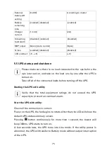
Page 70: ...ings The following table shows the indicator status and description Indicator Color Status Description Green ON The UPS is operating normally on Online or on High Efficiency mode Yellow ON The UPS is on Battery mode Yellow ON The UPS is on Bypass mode Flash The UPS is on Standby mode Red ON The UPS has an active alarm or fault Flash The UPS has an active alarm or fault ...

Page 71: ... 100ms 1s to scroll down the menu option Enter next menu tree Press this button for 100ms 1s to select the present menu option or enter next menu but do not change any setting Select one menu option Press this button for 100ms 1s to select the present menu option or enter next menu but do not change any setting Confirm the present setting Press this button for 1s to confirm the edited options and ...

Page 72: ... Beep every second Other Warning active Beep every second Battery output Beep every 4 seconds if battery low buzzer Beep every second Bypass output Beep every 2 minutes 5 2 LCD description The LCD backlight automatically dims after 2 minutes of inactivity except UPS is fault Press any button to wake up the screen ...

Page 73: ...e The UPS is operating on High Efficiency mode Once the mains are loss or abnormal the UPS would transfer to Line mode or Battery mode and the load is supplied continuously 1 The function could be enabled through the LCD setting or the software Winpower etc 2 It is reminded that the transfer time of UPS output from HE mode to battery mode is about 10ms But it is still too long for some sensitive l...

Page 74: ...ress the ESC button to cancel or return to the previous menu When starting the UPS the display is in the default UPS status summary screen Main menu Submenu Display information or Menu function UPS status status summary screen Alarm Battery charging Volt level remaining time mode Para Num Running time Measurements Load W VA Output Current A Output Voltage V Hz Input Voltage V Hz Battery V DC bus V...

Page 75: ...ltage 208V 220V 230V 240V Can be changed in Standby mode and Bypass mode 230V Output frequency autosensing 50HZ 60HZ autosensing Power strategy normal high efficiency converter normal Auto bypass enabled disabled enabled Auto restart enabled disabled Authorize the product to restart automatically when mains recovers after a complete battery discharge enabled Dry in Disabled SON SOFF Maintain bypas...

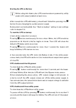
Page 76: ...ned on Take off all of the connected loads before turning off the UPS Starting the UPS with utility Verify that the total equipment ratings do not exceed the UPS capacity to prevent an overload alarm Start the UPS with utility Check all the connection is correct Power on the UPS the fan begins to rotate After that the LCD will show the default UPS status summary screen Pressing button continuously...

Page 77: ...0ms UPS starts to turn on A few seconds later the UPS turns into Battery mode If the utility power comes back the UPS will transfer to Line mode without output interruption of the UPS UPS shutdown with utility power To shut down the UPS with utility power Pressing button continuously for more than 3 seconds and the buzzer will beep 300ms After that the UPS will turn into Bypass mode at once When c...

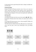
Page 78: ...tification and could change the settings to fit the user own requirements optimize the function of UPS The main menu In the default UPS status summary screen when pressing or 300ms the detailed information about alarm battery the system status would be shown In the default UPS status summary screen when pressing ESC 300ms the display would enter main menu tree The main menu tree includes six branc...

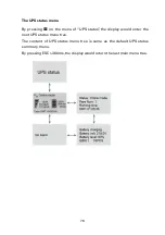
Page 79: ...g on the menu of UPS status the display would enter the next UPS status menu tree The content of UPS status menu tree is same as the default UPS status summary menu By pressing ESC 300ms the display would return the last main menu tree ...

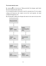
Page 80: ...ld enter the next measurements menu tree A lot of detailed useful information could be checked here Ex the output voltage and frequency the output current the load capacity the input voltage and frequency etc By pressing ESC 300ms the display will return to the last main menu tree ...

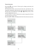
Page 81: ...recorded here The information includes the illustration the event code and the precise time of UPS when the event happened By press or 300ms all the events could be displayed one by one The max number of record is 100 when the number is larger than 100 the latest will replace the previous By pressing ESC 300ms the display would return the last main menu tree ...

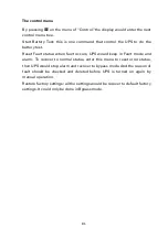
Page 82: ...us when fault occurs UPS would keep in Fault mode and alarm To recover to normal status enter this menu to reset error status then UPS would stop alarm and recover to bypass mode And the reason of fault should be checked and deleted before UPS is turned on again by manual operation Restore factory settings all the settings would be recover to default factory settings It could only be done in Bypas...

Page 83: ...82 ...

Page 84: ... The setting menu Please contact your local distributor for further information before using the settings Some settings would be changed the specification and some settings would enable or disable some functions The unsuitable option setting by user may result in potential failures or protecting function loss even directly damage the load battery or UPS AH setting could be set via RS232 or USB com...

Page 85: ...84 Example set rated output voltage value ...

Page 86: ...85 ...

Page 87: ...ll often have severely reduced runtimes Replace batteries at least every 4 years to keep units running at peak efficiency 7 2Transporting the UPS Please transport the UPS only in the original packaging to protect against shock and impact 7 3 Storing the equipment If you store the equipment for a long period recharge the battery every 6 months by connecting the UPS to utility power The EBM charge t...

Page 88: ...teries in a fire Batteries may explode when exposed to flame Do not open or mutilate the battery or batteries Released electrolyte is harmful to the skin and eyes and may be extremely toxic Take care if the battery is inadvertently grounded If grounded remove source from ground Contact with any part of a grounded battery may cause electrical shock The likelihood of such shock can be reduced if suc...

Page 89: ... the EBM connections are tight and there are adequate bend radius and strain relief exist for each cable Testing new batteries 1 Charge the batteries for 48 hours 2 By pressing on the menu of Control 3 Select Control then Single battery test The UPS can starts battery test only in line mode without active alarms During the battery test the UPS transfers to Battery mode and discharges the batteries...

Page 90: ... lead acid batteries and must be disposed of properly For more information contact your local recycling reuse or hazardous waste center Do not discard waste electrical or electronic equipment WEEE in the trash For proper disposal contact your local recycling reuse or hazardous waste center ...

Page 91: ... into the Event log Example Out short circuit Use the following troubleshooting chart to determine the UPS alarm condition 8 1Typical alarms and faults To check the Event log 1 By pressing on the menu of Event log 2 Scroll through the listed events or faults 3 The following table describes typical conditions Conditions Possible cause Action Fault code A107 Fault light flashes 1 beep every 1 second...

Page 92: ...es that the UPS get positive BUS over voltage fault Please contact your supplier Fault code F301 Fault lamp lights long Beep continuous Indicates that the UPS get negative BUS over voltage fault Please contact your supplier Fault code F302 Fault lamp lights long Beep continuous Indicates that the UPS get positive BUS under voltage fault Please contact your supplier Fault code F303 Fault lamp light...

Page 93: ...rt over voltage fault Remove some equipment from the UPS clear the fault code and try restart again Fault code F70C Fault lamp lights long Beep continuous Indicates that the UPS get inverter under voltage fault Remove some equipment from the UPS clear the fault code and try restart again Fault code F704 Fault lamp lights long Beep continuous Indicates that the UPS inverter fault Please contact you...

Page 94: ...4 Fault lamp lights long Beep continuous The UPS internal heat sink temperature is too high or a fan has failed At the warning level the UPS generates the alarm but remains in the current operating state If the temperature rises another 2 C the UPS transfers to Bypass mode or Standby mode Clear vents and remove any heat sources Allow the UPS to cool Ensure the airflow around the UPS is not restric...

Page 95: ...tem UPS mode normal converter HE different Check UPS OP mode Keep OP mode be the same Fault code F811 Fault lamp lights long Beep continuous Negative output power Please contact your supplier Fault code F00E Fault lamp lights long Beep continuous parallel cable disconnect Check if the parallel cable connect OK 8 2 Silencing the alarm Press the ESC Escape button 3s on the front panel display to sil...

Page 96: ...1 Power factor 1 Frequency regulation Follow utility power Online mode 50Hz 0 1Hz battery mode THDV Linear load 1 Non linear load 5 Overload 105 125 Load 10 minutes transfer to Bypass 125 150 Load 30 seconds transfer to Bypass 150 Load 0 5 seconds transfer to Bypass Environment Ambient temperature 0 50 Derating 50 above 40 C Relative humidity 95 Operating altitude 1000m Storage temperature with ba...

Page 97: ...er Load Devices or equipment connected to the UPS output HE mode Operating mode by which the load is supplied directly by the AC source if it is within the tolerances defined by the user This mode reduces the consumption of electrical power Manual bypass Rotary switch controlled by the user used to connect the loads directly to the AC source Transfer of the load to the manual bypass enables UPS ma...

Page 98: ...0 614 40029 00 ...

Reviews: