background image

4

Instruction Book    

IB182942EN   July 2018   www.eaton.com
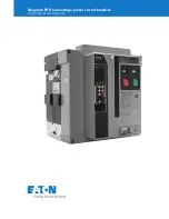
DST-2-VR

+

VR-Series

+

 Replacement Circuit Breaker

SECTION 1:   INTRODUCTION

This instruction booklet provides information on receiving and 

handling, storage, installation, operation and maintenance of the 

DST-2 VR-Series

+

 vacuum replacement circuit breaker. The Vacuum 

Replacement circuit breakers (also referred to as VR-Series

+

) are 

designed to be used in existing Federal Pacific type DST-2 metal-clad 

switchgear. The VR-Series

+

 circuit breakers provide superior electrical 

and mechanical performance as compared to the design ratings 

of the original circuit breaker. VR-Series

+

 circuit breakers provide 

reliable control, protection and performance, with ease of handling 

and maintenance. Like ratings of the VR-Series

+

 circuit breakers are 

interchangeable with each other.
The VR-Series

+

 circuit breaker element offers:

• 

10-year or 10,000 operation scheduled maintenance intervals.


When applied in “usual service conditions” as defined by IEEE 

C37.04-1999, the VR-Series

+

 circuit breaker element requires 

maintenance only once every ten years or ten thousand 

operations, which ever comes first.

otte:

N

See Inspection & Maintenance section in this booklet for details.

• 

Increased mechanical endurance.

 Circuit breakers in repetitive 

duty applications offer 50% more operations over conventional 

vacuum circuit breaker elements before parts replacement may 

be needed.

• 

Increased short circuit capability.

 The VR-Series

+

 circuit breaker 

short circuit capability can be increased to 41 kA, provided a bus 

bracing study is performed and the switchgear is adequately 

braced to meet the requirements per IEEE C37.59.

Use this instruction bulletin in conjunction with the technical 

information provided with the original equipment order which 

includes electrical control schematic and wiring diagrams, outline 

diagrams, installations plans, and procedures for installation and 

maintenance of accessory items.
Satisfactory performance is dependent on proper application, correct 

installation, and adequate maintenance. It is very important that 

this installation and maintenance instruction booklet be read and 

followed closely to achieve optimum performance and a long useful 

circuit breaker life in its application.

1.1   VISUAL INSTRUCTION BOOKLET ESSENTIALS

Eaton provides additional documentation designed to enhance the 

technical information provided in this instruction booklet for the 

VR-Series

+

 circuit breakers. The Visual Instruction Booklet Essentials 

(VIBE) is a digital supplemental booklet featuring user interactive 

content and informative videos intended to assist with the 

maintenance of the VR-Series

+

 circuit breaker. The VIBE document is 

available for immediate download at www.eaton.com/VR-Series.

Figurt 1.1. Quick Rtsponst Codt

VR-Series

+

 QR Code

1.2   QUICK RESPONSE CODE

VR-Series

+

 circuit breakers have a quick response code (QR Code) 

on the escutcheon of the circuit breaker front cover. This QR Code is 

a matrix barcode that provides direct access to download VR-Series

+


specific documentation, such as product instruction booklets and the 

VIBE documentation. See Figure 1.1 for the featured VR-Series

+

 QR 

Code.

otte:

N

A smart phone with an adequate QR Code Scanner application must be 

used. Downloading content may incur data charges from the mobile service 
provider. 

 WARNING

SATISFACTORY PERFORMANCE OF THESE CIRCUIT BREAKERS IS 

CONTINGENT UPON PROPER APPLICATION, CORRECT INSTALLATION 

AND ADEQUATE MAINTENANCE. THIS INSTRUCTION BOOKLET MUST 

BE CAREFULLY READ AND FOLLOWED IN ORDER TO OBTAIN OPTIMUM 

PERFORMANCE FOR LONG USEFUL LIFE OF THE CIRCUIT BREAKERS. IT IS 

FURTHER RECOMMENDED THAT THE INSTALLATION BE PERFORMED BY 

AN EATON TRAINED ENGINEER OR TECHNICIAN.

VR-SERIES

+

 CIRCUIT BREAKERS ARE PROTECTIVE DEVICES, AS SUCH, 

THEY ARE MAXIMUM RATED DEVICES. THEREFORE, THEY SHOULD NOT 

UNDER ANY CIRCUMSTANCE BE APPLIED OUTSIDE THEIR NAMEPLATE 

RATINGS.

ALL POSSIBLE CONTINGENCIES WHICH MIGHT ARISE DURING 

INSTALLATION, OPERATION, OR MAINTENANCE, AND ALL DETAILS 

AND VARIATIONS OF THIS EQUIPMENT ARE NOT COVERED BY THESE 

INSTRUCTIONS. IF FURTHER INFORMATION IS DESIRED BY THE 

PURCHASER REGARDING A PARTICULAR INSTALLATION, OPERATION, OR 

MAINTENANCE OF THIS EQUIPMENT, THE LOCAL EATON REPRESENTATIVE 

SHOULD BE CONTACTED.

1.3   AVAILABLE DST-2

-VR

+

 CIRCUIT BREAKERS

Refer to Table 1.

Summary of Contents for DST-2-15-500

Page 1: ...Instruction Book IB182942EN DST 2 VR VR Series Replacement Circuit Breaker DST 2 VR 250 2000A Shown July 2018 Supersedes March 2018 Effective...

Page 2: ...ions of this equipment do not purport to be covered by these instructions If further information is desired by purchaser regarding his particular installation operation or maintenance of particular eq...

Page 3: ...ERATION CHECK 21 5 4 VACUUM INTERRUPTER INTEGRITY 21 5 5 LOW FREQUENCY WITHSTAND TEST INSULATION CHECK 21 5 6 CONTACT EROSION AND WIPE 21 5 7 PRIMARY CIRCUIT RESISTANCE 21 5 8 ELECTRICAL OPERATIONS CH...

Page 4: ...portant that this installation and maintenance instruction booklet be read and followed closely to achieve optimum performance and a long useful circuit breaker life in its application 1 1 VISUAL INST...

Page 5: ...Latching Momentary Capabilities kV MVA Amps K Low Freq kV RMS Impulse kV Peak I kA RMS KI kA RMS kA RMS Peak DST 2 7 5 500 DST 2 7 5 VR 500 8 25 500 1200 2000 1 25 36 95 33 41 66 111 DST 2 15 500 DST...

Page 6: ...on com DST 2 VR VR Series Replacement Circuit Breaker Table 2 DST 2 VR Dimensions Circuit Breaker Type Existing Circuit Breaker Rated Continuous Current at 60 Hz Amps A B C D E F DST 2 VR 1200 2000 65...

Page 7: ...est coupler engaged Failure to disconnect the test coupler could result in an electrical shock leading to death severe personal injury equipment damage and or improper operation Do not work on a close...

Page 8: ...and other components If damaged or loss is detected file claims immediately with the carrier and notify an Eaton representative Tools and Accessories Maintenance Tool Style 94C9506G01 This tool is us...

Page 9: ...ition before placing it in to storage The circuit breaker is shipped with its contacts open and closing springs discharged The indicators on the front cover should confirm this Insert the end of the m...

Page 10: ...w of DST 2 VR Front External View 1 Lock Out Tag Out 5 Manual Charging Socket 9 Push To Close Button 2 Levering In Access 6 Spring Charged Discharged Indicator 10 Interlock Pedal 3 Handle 7 Operations...

Page 11: ...T 2 VR VR Series Replacement Circuit Breaker Figure 3 3 b Rear External View of DST 2 VR Rear External View 1 Lifting Points 4 Anti Rotation Self Adjuster Optional 2 Secondary Disconnects 5 Ground Con...

Page 12: ...t is assembled at the factory as a unit to assure correct dimensional relationships between working components Three interrupter assemblies are used per circuit breaker Each vacuum interrupter assembl...

Page 13: ...ER CONTACTS ARE CLOSED OR THE CLOSING SPRINGS ARE CHARGED THE CIRCUIT BREAKER CONTACTS MAY OPEN OR THE CLOSING SPRINGS DISCHARGE CAUSING CRUSHING INJURY DISCHARGE THE SPRINGS AND OPEN THE CIRCUIT BREA...

Page 14: ...This is the anti pump function 4 4 1 TIMING The opening and closing times for the circuit breakers vary depending upon the control voltage power rating environment and test equipment Differences in ti...

Page 15: ...est and Connect positions OPERATION C and NO C and NC C and NO C and NO C and NC C and NO Brown Switch Black Switch Black Switch Brown Switch SWITCH TERMINAL LS1 bb LS2 aa LS2 bb LC PS1 PS2 Circuit Br...

Page 16: ...ring system tripping and spring release interlocks perform the following a Set the breaker mechanically trip free during the first 4 inches of travel into the cell and whenever the breaker receives a...

Page 17: ...Cover Removed VR Series Circuit Breaker Element Mechanism 1 LH Closing Spring 5 Spring Release Assembly 9 Manual Charge Socket 2 Latch Check Switch To Rear of Motor Cutoff Switch 6 Shunt Trip Assembly...

Page 18: ...eaker Closed Springs Charged 2 1 3 4 5 6 7 8 9 10 11 12 13 14 Closing Cam and Trip Linkage 1 Spring Release Close Latch 6 Ratchet Wheel 11 Anti Close Interlock 2 Pole Shaft 7 Spring Crank 12 Motor Rat...

Page 19: ...2 Main Link 6 Cam Shaft 10 Trip Latch Reset Spring 3 Operating Rod 7 Banana Link 11 Shunt Trip Lever 4 Pole Shaft 8 Trip latch 12 Shunt Trip Coil 4 1 2 3 5 6 7 8 9 10 11 12 4 8 a Circuit Breaker Open...

Page 20: ...a cell containing an MOC until after the switch has been properly adjusted WARNING MEASUREMENTS AND ADJUSTMENTS SHOULD NEVER BE ATTEMPTED IN AN ENERGIZED STRUCTURE IF THE STRUCTURE CANNOT BE DE ENERGI...

Page 21: ...YS REMOVE THE MAINTENANCE TOOL AFTER CHARGING THE SPRING FAILURE TO REMOVE THE MAINTENANCE TOOL FROM THE BREAKER COULD CAUSE INJURY TO PERSONNEL AND OR EQUIPMENT DAMAGE IF THE BREAKER WAS TO CLOSE Clo...

Page 22: ...n The test position can be verified by the inability to move the breaker in or out the Interlock Pedal is in the up position and the cell label test is visible on the floor of the cell in front of the...

Page 23: ...onnect position can be verified by the inability to move the breaker in or out the Interlock Pedal is up and has released the trip mechanism and the cell label operating is visible on the floor of the...

Page 24: ...s DISCHARGED and that the main contact status indicator reads OPEN Manually trip close and trip the breaker as needed to obtain this status Note N The motor cutoff switch is located on the lower cover...

Page 25: ...so that the circuit breaker could be closed It must be returned to the fully withdrawn condition prior to insertion in the circuit breaker compartment b From the withdrawn position align the center g...

Page 26: ...al of the circuit breaker Note N For Canadian versions with separate disconnect and test positions it will stop at the test position Electrical and mechanical tests of the circuit breaker can be perfo...

Page 27: ...and retest or replace Insulation Integrity Main circuit to ground Withstand 15kV 60Hz for 1 Minute 5kV Rating Hi pot Tester Clean and retest or replace Control circuit to ground Charging Motor discon...

Page 28: ...ommended that the equipment be capable of delivering 25 milliamperes for one minute The current delivery capability of 25 mA ac applies when all three vacuum interrupters are tested in parallel If ind...

Page 29: ...ressed in micro ohms Repeat for the remaining two poles The resistance should not exceed the factory test levels more than 200 as stated in IEEE C37 09 Factory test levels are recorded on the circuit...

Page 30: ...ol Mounting Testing Locations by Circuit Breaker Type CIRCUIT BREAKER DESIGNATION APPROXIMATE MECHANISM CHASSIS WIDTH INCH LOWER MOUNTING HOLE LOWER MOUNTING HOLE MARKER PLACEMENT HOLE VR Series 18 A1...

Page 31: ...a sheet of paper that can be kept as a record of the test Record the date of the test person conducting the test circuit breaker serial number and the operations counter on the tape or paper Figures 6...

Page 32: ...Marker Interface Cam Marker CloSure Tool TM 15 O 15 O Figure 6 13 Determining the Distance Traveled Figure 6 14 Illustrative Testing Tape Sample Figure 6 12 Evaluate the CloSure Performance Date of Br...

Page 33: ...nt requires maintenance only once every ten years or ten thousand operations which ever comes first After a ten year service interval or when ten thousand operations have been reached contact your loc...

Page 34: ...urned Motor Cut Off Contacts open or burned Trip Coil Assembly Clapper fails to reset Closing sound but no close Pole Shaft Not open fully Trip Latch Reset Spring Damaged or missing Trip Bar D Shaft F...

Page 35: ...SWITCH Circuit Breaker Auxiliary Switch 94C9525G13 5 POSITION SWITCH Circuit Breaker Position Switch PS1 94C9525H06 6 POSITION SWITCH Circuit Breaker Position Switch PS2 94C9525H07 7 LATCH CHECK SWITC...

Page 36: ...ulevard Cleveland OH 44122 United States Eaton com 2018 Eaton All Rights Reserved Printed in USA Publication No IB182942EN July 2018 Eaton is a registered trademark All trademarks are property of thei...

Reviews: