Effective
10
/00
IL 33-K2C-3
Page 24
For Kits Supplied with a PT Module and / or
Breaker Mounted CPT Only.
STEP 11: FINAL CONNECTION OF THE PT AND
/ OR HV WIRES
I.
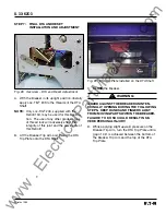
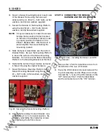
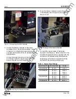
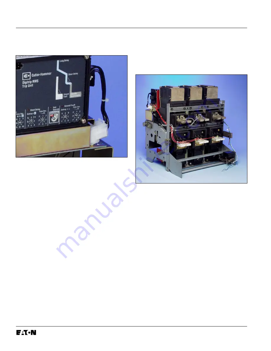
Install the Aux. CT Harness between the Trip
Unit and the Aux. CT Module.
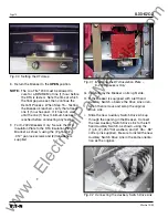
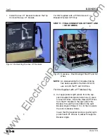
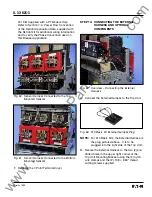
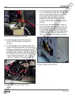
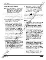
Fig. 45 Overview – Final Routing of the PT and HV
Wires
NOTE:
An adequate length of insulated tubing
has been supplied in the Retrofit Kit for
use on both the PT and HV Wires.
For Kits Supplied with a PT Module Only.
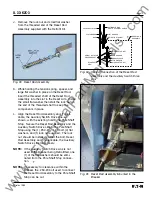
A. Cut appropriate length pieces from the sup-
plied insulated tubing and install one (1) piece
on each PT Wire. Route the three (3) PT Wires
from the PT Module to the right side of the
Breaker, through the hole drilled in the right
Breaker Angle in Steps 3 C or D, then towards
the bottom Breaker Stabs.
Insure that the insulated tubing is positioned to
protect each PT Wire as it passes through the
Breaker Angle.
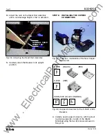
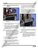
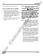
Fig. 44 Connecting the Aux. CT Harness
www
. ElectricalPartManuals
. com


