


IL
33-K2C-3
Page 2
Effective 10/00
Description
Introduction .......................................................... 4
Before Beginning the Retrofit Process
Identify the Breaker and the Retrofit Kit ................ 5
Following the Icons to a Successful Retrofit ......... 5
Step 1:
General Breaker Preparation .............. 6
Step 2:
Preparing the Breaker for
Retrofitting ............................................ 7
Step 3:
Drilling the Breaker Angles ................. 8
Step 4:
Preparing the DTA Assembly for
Installation ............................................ 9
Step 5:
Installing the DTA Assembly in
the Breaker ......................................... 11
Step 6:
Installing the Breaker Mounted
CPT on the DTA Mounting Angle ...... 13
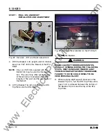
Step 7:
Final DTA and Reset
Installation and Adjustment .............. 17
Step 8:
Installing the Copper Connectors .... 20
Step 9:
Preparing the Trip Unit Assembly .... 21
Step 10:
Installing the Trip Unit on the
Breaker .............................................. 23
Step 11:
Final Connection of the PT
and / or HV Wires ............................. 24
Step 12:
Installing the Sensors ................ 27, 28
Step 13:
Connecting the Sensor Harness
and the DTA Harness ....................... 29
Step 14:
Connecting the External Harness
and Optional Components .............. 31
Step 15:
Testing the Breaker .......................... 33
Step 16:
Mounting the Cell Harness .............. 34
CONTENTS
Step 17:
Installing the Retrofitted Breaker in
the Cell .............................................. 34
Figures
1
Original Electromechanical Trip Units ............ 7
2. Removing the Glastic Moldings ..................... 7
3. Drilling Plan “A” – Front View ......................... 8
4. Optional Drilling Plan”A” ................................ 8
5. Drilling Plan “B” – Front View ......................... 9
6. Overview – DTA Assembly ............................. 9
7. Optional DTA Mounting Location ................... 9
8. DTA Mounted to the DTA Mounting Angle ... 10
9. Connections at the 2- Point Terminal
Block ............................................................ 10
10. Location of the DTA Insulation Plate
Mounting Bracket......................................... 10
11. Auxiliary Switch Assembly ........................... 10
12. Correct Installation of the Auxiliary Switch
Assembly ...................................................... 11
13. Overview – DTA Assembly installed in the
Breaker ......................................................... 11
14. Installing the DTA Assembly ........................ 12
15. Correct Wiring Harness Position .................. 12
16. Spacers Installed with the DTA Assembly ... 12
17. Routing of the DTA Extension Harness ........ 13
18. Overview – CPT Installed in the Breaker ..... 13
19. CPT Orientation and Screw Location .......... 14
20. Bracket Mounted to the CPT Insulation
Barrier ........................................................... 14
Digitrip Retrofit System for the
ITE K-Line Breakers: K-1600
(Black or Red), KDON-1600
(Black or Red), and K-2000 (Red)
www
. ElectricalPartManuals
. com


