


For more information visit: www.eaton.com
IB140042EN
Instructional Booklet
Page
40
Effective: May 2015
ATC-300 /900 Breaker Based Transfer Switch
Step 7:
To change or add a setpoint, select
Yes
when the
“Change Setpoints” message appears on the screen. Use
the
<Step/Enter>
pushbutton to step through the set-
points.
Use the
<Increase>
and
<Decrease>
pushbuttons to
change the setpoint.
When finished scrolling through and changing the desired
setpoints, answer
Yes
when the “Save Setpoints?” ques-
tion appears on the screen. The display will return to the
default screen.
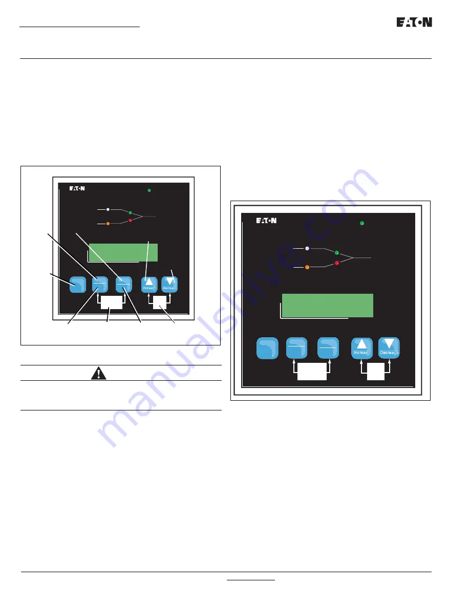
Figure 43. ATC-300 Pushbuttons
Step 8:
Manually start the engine generator at the generator con-
troller (Figure 43). Check that the generator is running
and the
Source 2 Available
amber LED is lit. Press the
<Step/Enter>
pushbutton, step through the phase volt-
ages, frequency, and message display. If the source mes-
sage indicates that the source is Good, shut down the
generator and place the Genset controller in the Auto-
operating position. If the message indicates a problem
with the source, the setpoints should be reviewed and the
generator checked for proper voltage and frequency out-
put.
Step 9:
Initiate a Load Test from the front panel of the ATC-300
(Figure 44). This may be done by setting the engine test
setpoint to:
1 Load Test
then saving the setpoints. Once the engine test setpoint
has been changed and saved, press the
<Engine Test>
pushbutton twice. The generator should start, the ATS
should transfer and run on the generator for the set test
interval, then proceed to a TDEN countdown and return to
Source 1. While the ATS is connected to Source 2, use a
voltmeter to check for correct system voltage on the load
terminals of the ATS. Check all phases on a 3-phase sys-
tem. Voltage measurements should be taken phase to
phase and phase to neutral. A load test will cause a
momentary power outage during transfer.
Figure 44. ATC-300.
Step 10:
ATH3/ATV3 Controlled ATS Power Failure Test - Initiate
a Load Test by simulating an actual power failure.
1. This should be done by opening the upstream breaker
or fused disconnect switch.
2. If the ATS is Service Equipment Rated with no
upstream disconnect, use the Source 1 Control Cir-
cuit Fused Disconnect to simulate a power failure
(Figure 45).
The Source 1 Control Circuit Fused Disconnect can
be found in one of two places. The first would be
located directly beside the Source 1 breaker. The
second would be located on the transformer panel/
customer connection panel. The Source 1 Control
Circuit Fused Disconnect is the disconnect marked
Source 1. The disconnect switch should be in the
ON position for Source 1 operation. Turning the
switch to the OFF position will simulate a Source 1
power outage.
WARNING
THE GENERATOR SHOULD BE MANUALLY STARTED AND THE OUT-
PUT CHECKED AND VERIFIED BEFORE PROCEEDING TO STEP 8. IF
IMPROPER VOLTAGE/FREQUENCY IS APPLIED TO THE LOAD, THE
ATS MAY BE DAMAGED.
ATC-300
se
se
Source 1
Source 2
Available
Available
Connected
Connected
Load
Unit Status
Alarm
Reset
Engine
Test
Lamp
Test
Help
Step
Enter
Bypass
TDNE / TDEN
ALARM RESET
DECREASE
ENTER
INCREASE
STEP
BYPASS
TDNE/TDEN
LAMP TEST
ENGINE
TEST
HELP
ATC-300
se
se
Source 1
Source 2
Available
Available
Connected
Connected
Load
Unit Status
Alarm
Reset
Engine
Test
Lamp
Test
Help
Step
Enter
Bypass
TDNE / TDEN


