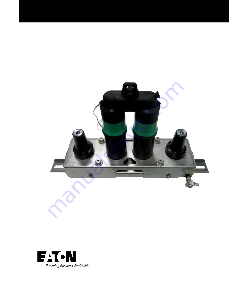
600 A 15, 25, and 28 kV class Cleer loadbreak connector system
installation instructions
COOPER POWER
SERIES
Loadbreak Apparatus
Connectors
MN650019EN
Effective March 2016Supersedes S600-100-1 March 2013
Page 1: ...00 A 15 25 and 28 kV class Cleer loadbreak connector system installation instructions COOPER POWER SERIES Loadbreak Apparatus Connectors MN650019EN Effective March 2016 Supersedes S600 100 1 March 201...
Page 2: ...NY EXISTING CONTRACT BETWEEN THE PARTIES ANY SUCH CONTRACT STATES THE ENTIRE OBLIGATION OF EATON THE CONTENTS OF THIS DOCUMENT SHALL NOT BECOME PART OF OR MODIFY ANY CONTRACT BETWEEN THE PARTIES In no...
Page 3: ...3 In line bracket installation instructions 3 Square bracket installation instructions 4 OPERATING INSTRUCTIONS Loadmake operation 5 Fault close 6 Loadbfreak operation 6 CABLE ISOLATION AND GROUNDING...
Page 4: ...afety information DANGER Hazardous voltage Contact with hazardous voltage will cause death or severe personal injury Follow all locally approved safety procedures when working around high and low volt...
Page 5: ...ng a visible ground It is then safe to perform work on the underground cable Read this manual first Read and understand the contents of this manual and follow all locally approved procedures and safet...
Page 6: ...OL T and 1 T OP II or BT TAP termination T OP II OR BT TAP TERMINATION BOL T TERMINATION SOURCE LOAD Figure 4 600 A loadbreak connector system with 2 BOL T terminations Figure 5 600 A loadbreak connec...
Page 7: ...ding to location marks made in Step 2 Step 4 With pivot support mounting feet assembly secure using supplied 5 16 hardware mount bracket with junction to pivot support mounting feet Step 5 Adjust brac...
Page 8: ...tes of enclosure See Figure 9 Note N The assembly should be secured with four 4 bolts using one upper and lower slot on each side of the bracket Step 2 Using supplied grounding clamps connect bracket...
Page 9: ...te 200 A loadbreak or 600 A deadbreak products to Cleer 600 A loadbreak bushings Failure to comply could lead to a fault that may result in death or serious injury WARNING High Voltage Do not close or...
Page 10: ...gs with a fast firm straight motion Minimum amount of travel of connector to break load is 9 230 mm Using the clampstick move the connector away from the bushings and place the metallic portion of one...
Page 11: ...source side loadbreak bushing See Figure 13 Figure 12 Remove C LCN connector LOAD SOURCE REMOVE LCN BOL T TERMINATION T OP II OR BT TAP TERMINATION Figure 13 Install 600 A loadbreak protective cap LOA...
Page 12: ...and obtain good footing Slam the elbow onto the bushing with one quick and continuous motion Figure 14 Remove 200 A loadbreak protective cap SOURCE 200 A LOADBREAK REDUCING TAP PLUG LOAD 200 A LOADBR...
Page 13: ...last operation push on the clampstick to seat the elbow all the way onto the bushing again This insures that the elbow is latched and was not dislodged during the latch ing check in previous step abo...
Page 14: ...st firm straight motion Minimum amount of travel of connector to break load is 9 230 mm See Figure 18 Using the clampstick move the connector away from the bushings and place the metallic portion of o...
Page 15: ...gh the load side 600 A loadbreak bushing interface to verify circuit is de energized See Figure 20 Step 6 Install grounding elbow If circuit is de energized install Cleer 600 A 15 25 kV grounding elbo...
Page 16: ...7 25 6 649 5 00 127 4 00 101 6 8 93 226 8 2 04 51 8 26 88 682 8 CONFIGURATION 1 CONFIGURATION 2 CONFIGURATION 3 Figure 22 In line mounting configurations and dimensions Mounting configurations and dim...
Page 17: ...5 mm 4 00 101 6 mm 3 55 90 2 mm 5 0 127 3 0 76 10 5 264 11 5 292 3 55 90 2 7 90 200 7 15 30 388 6 4 0 101 6 12 79 324 9 10 21 259 3 7 0 178 3 5 89 1 5 38 12 0 8 20 mm 2 0 51 mm 7 0 178 mm 7 0 178 mm 1...
Page 18: ...This page intentionally left blank 14 CLEER LOADBREAK CONNECTOR SYSTEM INSTALLATION INSTRUCTIONS MN650019EN March 2016...
Page 19: ...This page intentionally left blank 15 CLEER LOADBREAK CONNECTOR SYSTEM INSTALLATION INSTRUCTIONS MN650019EN March 2016...
Page 20: ...ates Eaton com cooperpowerseries 2016 Eaton All Rights Reserved Printed in USA Publication No MN650019EN Rev 00 Replaces S6001001 Rev 04 Eaton is a registered trademark All trademarks are property of...