11
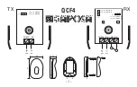
Figure 20
Seal Washer
Cap
Screw
End Cap
Seal
General Purpose Motors
S Series
Reassembly
39 Install cap screws (and seal washers when required, see informa-
tion below) in end cap.
On 97 cm
3
/r [5.9 in
3
/r] displacement motors or less, use seal washers.
Pre-tighten all screws to 2-5 Nm[15-40 lb-in]. Make sure Geroler
section seals are properly seated before torquing screws. Then torque
screws to 23 Nm[200 lb-in] in sequence, as shown in Fig. 21.
On 120 cm
3
/r [7.3 in
3
/r] displacement motors or larger, omit seal
washers. Pretighten all screws to 2-5 Nm [15-40 lb-in]. Make sure
Geroler section seals are properly seated before torquing screws. Then
torque screws to 34Nm [300 lb-in] in sequence, as shown in Fig. 21.
Note: Steps 41 through 45 cover mounting flange seal installation
without using a seal installation tool.
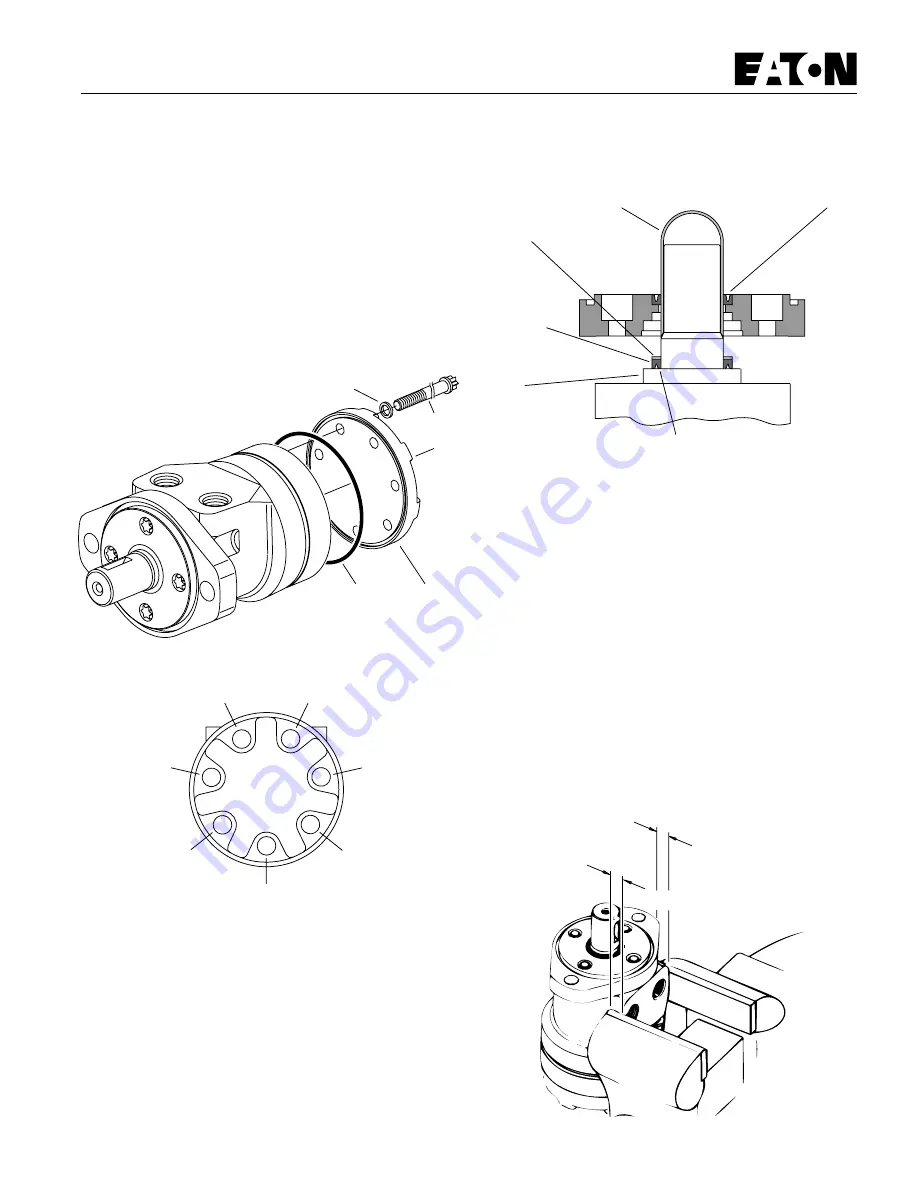
40 Clamp motor in vise with output shaft up, see Fig. 23. Remove cap
screws and flange.
41 Prepare seal seat of flange, see step 22.
42 Lubricate dust seal O.D. Install dust seal in flange. Make sure dust
seal is flush with flange, see step 24.
43 Install pressure seal flush against bearing race, see Fig. 22. Lightly
lubricate pressure seal O.D.
44 Place a seal sleeve or bullet over shaft. Twist flange down shaft
until flush against pressure seal. The pressure seal must enter into
seat evenly and gradually. Install 4 cap screws. Gradually and evenly
finger tighten cap screws (crisscross pattern). Then use a hand socket
wrench to lightly snug tighten screws until flange is flush against
housing. Do not tighen screws more than one full rotation at a time
(crisscross pattern).
45 Use a hand torque wrench to gradually and evenly tighten cap
screws (crisscross pattern) until they reach 28Nm[250 lb-in]. See
important information below.
Important: Do not use air socket wrench on cap scrdws for this type
of seal installation.
Important: Proper pressure seal installation is important. You must
remove cap screws and flange to examine seal condition. If you
have cut or damaged the pressure seal, you must replace it with a
new one. If seal is in good condition continue flange reassembly—
starting with procedure step 24, page 8.
Seal Sleeve
or Bullet
Pressure Seal Lips Toward Race
Figure 22
Back-up
Ring
(-009
and -010
Motors)
Lightly
Lubricate
Entire O.D.
of Pressure
Seal
Bearing
Race
Dust
Seal
5
7
1
3
2
4
6
Bolt Torquing Sequence
Figure 21
13 mm [.50 inch]
13 mm [.50 inch]
Figure 23
Summary of Contents for Char-Lynn S Series
Page 2: ...2...