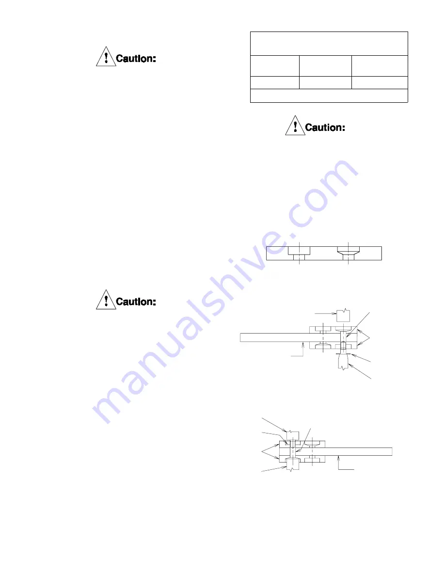
Figure 7
Figure 9
Friction Disc
Core
Rivet
Punch
Washer
Friction
Disc
Anvil
Figure 8
Rivet
Friction
Disc
Washer
Anvil Pin
Driver
Friction Disc Core
Use only genuine, Airflex friction
material. Use of material not of
Airflex origin may result in unpre-
dictable brake performance and/or
excessive wear of the brake
components.
4.3.6.1
Drill out the old rivets and remove and
discard the old friction discs.
4.3.6.2
Refer to Figure 7 and carefully examine the
counterbored holes in the new friction disc.
One set of counterbored holes is tapered
and designed to accept the rivet head,
while the other set of counterbored holes is
flat bottomed and designed to
accept the clinched end of the rivet.
4.3.6.3
Position the friction discs on both sides of
the disc core and align the rivet holes.
Remember, a tapered counterbored hole
on one friction disc will mate with a flat-
bottomed counterbored hole on the opposite
friction disc.
Manual setting of the rivets using a
punch very frequently results in
splitting of the clinched end of the
rivet. When this occurs, the rivet
will ultimately fail in service due to
fatigue. It is therefore recom-
mended that rivets be set using an
automatic rivet setting machine.
4.3.6.4
Insert a rivet through any hole and set using
a washer on the clinched end of the rivet. Be
sure to note the type of counterbored hole to
determine the position of the rivet head. See
Figures 8 and 9. Figure 8 shows machine-
setting and Figure 9 shows setting the rivet
manually. When setting manually, use an ar-
bor press and keep the setting tool square
to avoid splitting the rivet.
The clinched end of the rivet must
have a washer in place prior to
clinching. Failure to use the washer,
or use of excessive force, when
clinching the rivet will fracture the
friction lining.
TABLE 5
Friction Disc Repair Kits
Brake Size
Kit Part
Number
Rivet
Setting Tool
20DBB
107744D
153x1096
Dual disc brakes require two kits.
DBB 8104 PDF format
9
© Copyright Eaton Corp., 1998. All rights reserved.
(Revised: January, 1998)


