background image

4–20kVA Users Guide P-164000669 4–20kVA Users Guide P-164000669—Rev 10

17

33..33

U

UP

PS

S C

Coonnnneeccttiioonnss

NOTE

For installation and configuration of the Eaton bypass switch refer to the manual “Eaton
Bypass Power Module (BPM) User’s Guide P-164000628” supplied with the switch or
on the Eaton website.

UPS Connections

NOTE 1

Refer to “

3.2

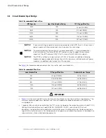
Circuit Breaker Input Ratings

” for breaker, terminal block, and wire sizing.

NOTE 2

Connection Diagrams can be found on

Figure 17

and on

Figure 18

.

To prevent electrical shock or damage to the equipment, verify that the Eaton 9PXM UPS is OFF before you
remove the terminal covers. The circuit breaker or disconnect switch must also be OFF at the AC input service
panel.

To install the UPS with an external bypass switch:

1.

Mount the bypass switch within sight of the UPS. If you do not have an Eaton bypass switch or the fuse
box or panel is out of sight, you must install a separate disconnect switch next to the UPS.

2.

The bypass switch should be mounted securely to a sturdy surface. You may need to turn the cabinet 90
degrees (on its side) to enable operator access to the switch handle.

3.

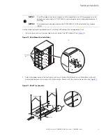
Remove the six screws on the bypass switch wiring cover and remove the cover. Remove any packing
material inside the bypass switch.

4.

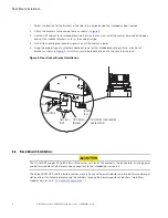
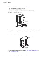
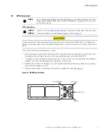
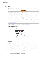
Remove the knockouts in the bottom of the BPM as needed for wiring. See

Figure 15

Figure 15. BPM Bypass Bottom

From UPS Output

To UPS Input

BPM Signal Wire

To Load

From Line

UPS Connections

Summary of Contents for 9PXM8S4K

Page 1: ...p n P 164000669 Revision 10 Eaton 9PXM UPS 4 20kVA Users Guide Eaton 9PXM UPS...

Page 2: ...as ss s A A E EM MC C S St ta at te em me en nt ts s FCC Part 15 NOTE This equipment has been tested and found to comply with the limits for a Class A digital device pursuant to part 15 of the FCC Ru...

Page 3: ...ce instructions This symbol indicates that you should not discard the product in the trash This product must be disposed of properly For more information contact your local recycling reuse or hazardou...

Page 4: ......

Page 5: ...iagrams 25 3 6 Bypass Overview 28 3 7 No Break Transfer from UPS Mode to Service Mode 29 3 8 Lock out Tag out 30 3 9 No Break Transfer from Service Bypass to UPS Mode 31 4 4 U UP PS S E Elle ec ct tr...

Page 6: ...he Event Log 70 7 9 Retrieving the Fault Log 70 7 10 Control Panel Operation 70 7 11 Display Functions 71 7 12 LCD Description 72 7 13 Display Status Indicators 72 7 14 Changing Parameter Settings 73...

Page 7: ...Breakers 98 10 4 Environmental and Safety 98 10 5 Battery Ratings 99 10 6 Output Run Times 99 10 7 Weights and Dimensions 99 10 8 Output Receptacles 100 10 9 Receptacle Circuit Breaker Ratings 101 1...

Page 8: ...viii 4 20kVA Users Guide P 164000669 4 20kVA Users Guide P 164000669 Rev 10 Table of Contents...

Page 9: ...re 18 UPS Input and Output Terminals 20 Figure 19 Bypass Switch Wiring Label and Terminal Blocks 21 Figure 20 UPS Input Control Signal Wiring for Maintenance Bypass 22 Figure 21 BPE to UPS Connector 2...

Page 10: ...EBM Battery Modules and Charger 60 Figure 55 Communication Ports 61 Figure 56 UPS Control Panel 71 Figure 57 LCD Display Status Indicators 72 Figure 58 Display Status Indicators 73 Figure 59 Start Scr...

Page 11: ...Positions 29 Table 4 BPM Dimensions 33 Table 5 UPS Recommended Breaker Sizes 36 Table 6 UPS Recommended Wire Sizes 36 Table 7 Electrical Input and Output 97 Table 8 Power Ratings 97 Table 9 Circuit B...

Page 12: ...xii 4 20kVA Users Guide P 164000669 4 20kVA Users Guide P 164000669 Rev 10 List of Tables...

Page 13: ...h removable front panels All power modules share the load requirements equally For example three power modules are capable of supplying a total of 12 kVA If a load requires only 6 kVA each power modul...

Page 14: ...ation en entr e et en sortie pour l onduleur Ceux ci doivent se trouver dans le p rim tre de l onduleur et tre faciles d acc s En ce qui concerne l unit de prise la prise sert d appareil de d connexio...

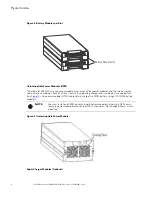
Page 15: ...mounted UPS installation see Figure 1 Figure 1 Eight and Twelve Slot Cabinets Front View Caster Tray Control Panel Front Covers 8 Slot UPS 12 Slot UPS The rear UPS panel features power input and outp...

Page 16: ...ommunication Ports Communication Card Slots DB 9 Port USB Port Knockout Recepticle Panels Twelve slot chassis shown Eight slot similar Power Modules UPS power modules UPMs are installed in the left ha...

Page 17: ...slot can contain up to eleven two battery slots Each two battery slot contains two battery modules that can be removed and installed separately from the battery slots in the chassis A battery module...

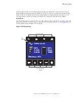
Page 18: ...to six modules Each 4kVA has a built in 5 amp battery charger and is cooled by two cooling fans see Figure 5 One power module UPM is able to fully charge five 9PXM battery strings 10 9PXM battery modu...

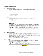
Page 19: ...super charger is able to fully charge 22 9PXM battery strings or 44 individual battery modules Control Panel The UPS control panel has a graphical LCD screen light indicators and function buttons It p...

Page 20: ...8 4 20kVA Users Guide P 164000669 4 20kVA Users Guide P 164000669 Rev 10 Physical Features...

Page 21: ...d the back of the cabinet Do NOT attempt to move the cabinet with the power modules or battery modules installed External battery cabinets may be installed with bases tight against the UPS cabinet bas...

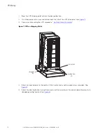
Page 22: ...Figure 7 3 If you are rack mounting the UPS proceed to 2 6 Rack Mount Installation Figure 7 UPS on Shipping Pallet Caster Cart Leveling Feet 4 Bracket Bolts 8 4 Attach the supplied ramp to the pallet...

Page 23: ...cabinet continue to 5 2 Standard Battery Cabinet Installation or 5 1 Battery Cabinet Options 9 Continue to 3 1 Installation of the UPS with an External Bypass Switch or 4 2 UPS Electrical Installation...

Page 24: ...cket as shown in Figure 9 All screws must be properly driven into the structural material Figure 9 Floor Anchor Bracket Installation Floor Anchor Bracket Floor Bolt Slots Mount Bolts Spacer Leveling F...

Page 25: ...following mounting procedures to install the UPS cabinet into the equipment rack 1 Install rack mount ears two per side on each side of the UPS cabinet See Figure 10 Figure 10 Rack Mount Ear installa...

Page 26: ...Caster Tray UPS Cabinet 4 Carefully slide the UPS from the caster tray onto the rail tray in the equipment rack until the rack mount ears of the cabinet are almost flush with the front vertical rails...

Page 27: ...licensed electrician should perform the electrical installation in this section NOTE For installation and configuration of the Eaton bypass switch refer to the manual Eaton Bypass Power Module BPM Use...

Page 28: ...maximum allotted number of power modules no additional input ampacity will be required See Table 2 for recommended conductor sizes to wire the input circuit breakers Table 2 Recommended Wire Sizes In...

Page 29: ...The circuit breaker or disconnect switch must also be OFF at the AC input service panel To install the UPS with an external bypass switch 1 Mount the bypass switch within sight of the UPS If you do n...

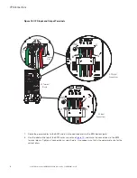
Page 30: ...t Terminals Terminal Cover 5 At the AC Input terminal make sure to wire the UPS for the proper input voltage as shown in Figure 17 Split phase power modules provide a 2 phase output which can be confi...

Page 31: ...inal blocks on the rear panel see Figure 18 a Insert the L1 N and L2 cable ends into the applicable terminal slots on the terminal block b Insert the G GND cable end into the ground lug on the rear pa...

Page 32: ...AC Terminal Blocks Lug Screws Terminal Block Ground Lug 7 Route the power cables to the BPM and install conduit adapters to the BPM bottom plate 8 Use the label on the top of the BPM access cover and...

Page 33: ...erminal Block AC TO UPS INPUT L2 N L1 L2 N L1 AC TO LOADS CABLES FROM UPS AND AC INPUT OUTPUT THROUGH BPM BOTTOM ACESS PLATE AC FROM UPS OUTPUT L2 N L1 L2 N L1 Upper BPM Terminal Block Lower BPM Termi...

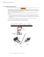
Page 34: ...nal CN13 on the rear of the UPS See Figure 20 For conduit requirements consult your local electrical code 2 Place the signal wires through the proper conduit or grommet to the terminal block in the BP...

Page 35: ...For BPE connections as shown in a Connect up the 4 wires from the BPE to the 9PXM per the attached drawing and using the 3 pin connector see Figure 21 Figure 21 BPE to UPS Connector 3 2 1 4 3 2 1 4 3...

Page 36: ...ormally open Menu Measurements Control Settings Event Log Fault Log Identification Register product Settings In Out settings Local settings On Off settings Battery settings Input Signals Comm Settings...

Page 37: ...side of the switch must be connected as described in NOTE 3 The customer must size the AC circuit conductors All AC circuit conductors including the neutral conductor must be the same size ampacity ha...

Page 38: ...T TO EBM 2 TO NEXT EBM If installed DC INPUT EBM 1 EBM 2 CN3 CN4 8 9 7 6 5 4 3 2 1 7 6 5 4 3 2 1 UPS CN4 EBM CN4 Supplied Connectors Pin numbering is right to left Input Signal connections Typical A A...

Page 39: ...UT EBM 1 EBM 2 CN3 CN4 8 9 7 6 5 4 3 2 1 7 6 5 4 3 2 1 UPS CN4 EBM CN4 Supplied Connectors Pin numbering is right to left Input Signal connections Typical A A G L2 L1 N G L2 L1 N NO CONTACT Force Bypa...

Page 40: ...e the UPS output Do not attempt to push the red interlock button or attempt to move the bypass switch handle if the UPS is operating on battery power If you have any questions or problems with the byp...

Page 41: ...S Se er rv viic ce e M Mo od de e Failure to understand the correct bypass sequence and position may cause the critical load to be dropped Damage to the power modules or the Bypass switch can occur If...

Page 42: ...nected from AC power Ensure that the UPS is off and the terminals are completely de energized before performing any maintenance on the UPS Figure 28 Bypass From LINE to SERVICE Rotate switch to SERVIC...

Page 43: ...the critical load to be dropped Damage to the power modules or the Bypass switch can occur If the UPS remains in Bypass Mode and incoming AC power is lost the load is automatically dropped The UPS mu...

Page 44: ...n and turn the switch to UPS see Figure 31 NOTE 1 Pressing the red button sends the UPS into Bypass Mode This allows the UPS output to synchronize with utility for safe uninterrupted transfer NOTE 2 I...

Page 45: ...button on the front panel display The main menu screen appears see Press the button to select Control Press the button Control menu displays Press the button to select Go back Normal Press the button...

Page 46: ...34 4 20kVA Users Guide P 164000669 4 20kVA Users Guide P 164000669 Rev 10 No Break Transfer from Service Bypass to UPS Mode...

Page 47: ...t used the UPS input may be hardwired through conduit to a main power source circuit breaker and the UPS output may either be hardwired to a circuit breaker in a distribution panel as shown in Figure...

Page 48: ...ed Wire Sizes Input Breaker Size 75 Copper Wire Size Conductor Screw Tourqe 25A 5 3 mm2 10 AWG 4 0 Nm 35 lb in 50A 8 4 mm2 8 AWG 4 5 Nm 40 lb in 80A 21 2 mm2 4 AWG 5 1 Nm 45 lb in 100A 33 6 mm2 2 AWG...

Page 49: ...the Eaton 9PXM UPS is OFF before you remove the terminal covers The circuit breaker or disconnect switch must also be OFF at the AC input service panel To install the UPS without an external bypass sw...

Page 50: ...ower modules provide a 2 phase output which can be configured as output voltages 110 110 for 220 120 120 for 240 120 120 for 208 or 127 127 for 220 Vac as selected through the front panel display 7 15...

Page 51: ...conduit systems and not shared with other electrical circuits a Insert the L1 N and L2 cable ends into the applicable terminal slots on the terminal block b Insert the G GND cable end into the ground...

Page 52: ...must size the AC circuit conductors All AC circuit conductors including the neutral conductor must be the same size ampacity have the same rating 75 C copper wire and be sized according to the input...

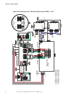
Page 53: ...0 240 Output 127 220 Input 127 220 Output INPUT OUTPUT POWER BUS BAR CN13 UPS NO AUX NO AUX NC 3 2 1 INPUT FROM FACILITY EXTERNAL DC AC OUTPUT AC INPUT UPS UPS INPUT SIGNALS CN3 CN4 CN6 CN6 CN4 5 6 AC...

Page 54: ...42 4 20kVA Users Guide P 164000669 4 20kVA Users Guide P 164000669 Rev 10 System Wiring Diagram...

Page 55: ...s are available for a Connected battery cabinet 5 3 Connected Battery Cabinet With No AC Input used for extended runtime battery support only There is no capability of using a super charger module wit...

Page 56: ...t the proper location of cabinet to cabinet DC wiring is on the lower left of the rear panel All of the slots in the Standard 8 and 12 slot battery cabinets can be populated with batteries Prepare the...

Page 57: ...shipped in the UPS and EBM accessory kit and do not come installed on the UPS or EBM chassis 1 Route the EBM DC input output cables to the terminal blocks as shown in Figure 38 NOTE Torque the screws...

Page 58: ...d be sure to set the number of external battery strings on the UPS LCD for calculating the runtime See 6 5 Initial Startup Parameters 5 5 3 3 C Co on nn ne ec ct te ed d B Ba at tt te er ry y C Ca ab...

Page 59: ...cabinet the proper location of cabinet to cabinet DC wiring is on the lower left of the rear panel All of the slots in the Standard 8 and 12 slot battery cabinets can be populated with batteries P Pr...

Page 60: ...PS and EBM accessory kit and do not come installed on the UPS or EBM chassis 5 Route the EBM DC input output cables to the terminal blocks as shown in Figure 41 NOTE Torque the screws holding all inpu...

Page 61: ...ing the runtime See 6 5 Initial Startup Parameters 5 5 4 4 C Co on nn ne ec ct te ed d B Ba at tt te er ry y C Ca ab biin ne et t W Wiit th h 1 12 20 0V VA AC C I In np pu ut t Make sure all AC power...

Page 62: ...pstream to the UPS repeat the setup as described in this section The battery cables are supplied inside the battery cabinet accessory kit In the UPS cabinet the proper location of cabinet to cabinet D...

Page 63: ...rews holding all input and output power conductors to the values specified in Table 2 6 Connect the EBM DC Cables to the applicable terminals by removing and reinstalling the screws onto the terminal...

Page 64: ...1 EBM 2 CAN OUT CN3 CAN OUT CN3 CAN IN CN4 CAN IN CN4 11 Connect the CAN cable ground wires to the EBM chassis NOTE Connect each CAN ground wires to separate screws on the chassis See Figure 46 Figure...

Page 65: ...e all electrical safety precautions Only qualified service personnel such as a licensed electrician should perform the battery cabinet installation Risk of electrical shock For the 120V 208V or 120V 2...

Page 66: ...ream to the UPS repeat the setup as described in this section The battery cables are supplied inside the battery cabinet accessory kit In the UPS cabinet the proper location of cabinet to cabinet DC w...

Page 67: ...holding all input and output power conductors to the values specified in Table 2 6 Connect the EBM DC Cables to the applicable terminals by removing and reinstalling the screws onto the terminal block...

Page 68: ...BM 1 EBM 2 CAN OUT CN3 CAN OUT CN3 CAN IN CN4 CAN IN CN4 11 Connect the CAN cable ground wires to the EBM chassis NOTE Connect each CAN ground wires to separate screws on the chassis See Figure 51 Fig...

Page 69: ...s Guide P 164000669 4 20kVA Users Guide P 164000669 Rev 10 57 Figure 52 EBM Emergency Disconnect Switch EBM Disconnect Switch 13 Proceed to Chapter 6 1 UPS Startup Connected Battery Cabinet With Split...

Page 70: ...58 4 20kVA Users Guide P 164000669 4 20kVA Users Guide P 164000669 Rev 10 Connected Battery Cabinet With Split Phase Input...

Page 71: ...installed in the left or right hand slots it takes two battery modules per slot to equal one battery string Removal of the power modules and battery modules is the reverse of these procedures Install...

Page 72: ...tery Modules Captive Screw 5 If you installed the optional battery cabinets EBMs install the battery modules using the same procedure as the UPS modules If applicable install the super charger in the...

Page 73: ...ircuit breaker If external battery cabinets are installed close the DC emergency disconnect switch button on the back of each external battery cabinet Insert the switch key supplied with the cabinet i...

Page 74: ...connect switch button on the back of each external battery cabinet Insert the switch key supplied with the cabinet into the button and turn clockwise 1 2 turn Pull the button out to close the switch T...

Page 75: ...ne power module is installed Set up the initial operating parameters through the front panel display see 6 5 Initial Startup Parameters 16 If applicable test proper operation of optional external cont...

Page 76: ...nput Measurement AC from UPS Output Measurement L1 to L2 11 to 12 7 to 8 N to L1 10 to 11 6 to 7 N to L2 10 to 12 6 to 8 For some installations there is no connection at terminals 6 8 10 or 12 8 Deter...

Page 77: ...18 Turn on the equipment that is connected to the UPS 19 If there is an external bypass switch turn it to UPS Otherwise close the load distribution circuit breaker s 6 6 5 5 I In niit tiia all S St t...

Page 78: ...equired output cannot be maintained with the loss of redundant power modules The alarm is essentially disabled with a redundancy level set at 0 6 Optional If you want the system to notify you when the...

Page 79: ...powered and protected 7 Make sure the UPS is in Online mode 7 7 2 2 U UP PS S S St ta an nd db by y M Mo od de e To place the UPS in standby Press the button on the front panel for three seconds The...

Page 80: ...ime All the LEDs go OFF The audio alarms stops 7 7 4 4 3 3 L Lo ow w B Ba at tt te er ry y W Wa ar rn niin ng g During discharge the low battery alarm is activated if the remaining runtime goes below...

Page 81: ...will transfer immediately 7 7 6 6 C Co on nf fiig gu ur riin ng g B By yp pa as ss s S Se et tt tiin ng gs s The following settings are available for configuring Bypass operation see Figure 64 Changi...

Page 82: ...ned due to bad conditions or failed if battery is not ok 7 7 7 7 3 3 L Lo ow w B Ba at tt te er ry y W Wa ar rn niin ng g During discharge the low battery alarm is activated if the remaining runtime g...

Page 83: ...ciency 94 Efficiency 94 100 2 7kW 3 0kVA 100 19min 1EBM Online mode 7 7 1 11 1 D Diis sp plla ay y F Fu un nc ct tiio on ns s Press the Enter button to activate the menu options Use the two middle but...

Page 84: ...saver The LCD backlight automatically dims after 10 minutes of inactivity Press any button to restore the screen Figure 57 LCD Display Status Indicators Operation status Load equipment status Efficien...

Page 85: ...attery Warning settings Capacity 0 100 Runtime 0mn 60mn The alarm triggers when the set percentage of battery capacity or remaining back up time is reached High Efficiency Mode The UPS is operating on...

Page 86: ...The status screen shows the status of the installed units Figure 60 Status Screen Menu UPS 4 1 6 4 EBM EBM 1 1 5 EBM 2 1 5 EBM 3 1 6 EBM 4 1 2 Efficiency 94 100 10 1kW 10 1kV 100 19min 24 Press to st...

Page 87: ...age Cumulat Power Usage Measurements Measurements Total Load Load Phase 1 N L1 Load Phase 2 N L2 Input Bypass Measurements Total Output Load Phase 2 N L2 Input Bypass Output Efficiency Measurements Ou...

Page 88: ...ult state Restore factory set Reset average power Control Go to bypass Start battery test Reset fault state Restore factory set Reset average power Control Go to bypass Start battery test Reset fault...

Page 89: ...ble User password settings Settings Local settings Language Date time LCD Audible alarm LCD settings Audible alarm Enabled Disable on battery Always disabled English Fran ais Espanol Menus status noti...

Page 90: ...iciency mode Disabled Enabled Protected Bypass Enabled Disabled Overload prealarm 100 Byp freq limit Byp volt min limit Byp volt max limit Redundancy Level 0 Level 3 Level 4 4 Hz 12 12 110V 120V 127V...

Page 91: ...400 W 600 W 1000 W 1500 W 2000 W Select On Off Settings Auto restart Enabled Disabled Site Wiring Fault Disabled Enabled Shut off level Enabled Disabled Timer 10s 180s When mains recover during a shu...

Page 92: ...tection Auto Detection Manual EBM set External battery Auto Detection 1 BM External battery Manual EBM set 0 Strings External battery Manual batt set 0 AH Advanced Battery Mode Enabled Disabled In ABM...

Page 93: ...assword enable User password settings Settings Emergency power off Remote On Off On Generator Force Bypass Maintain Bypass Input Signals Emergency Power Off Enabled Disabled Remote On Off Disabled Nor...

Page 94: ...e Command Shutdown command Battery notice delay Comm Settings Com Settings Send command Output off Off delay 10s Output off Minislot 2 remote off Minislot 2 remote off Comm Settings Minislot 2 reset M...

Page 95: ...nt Log Fault Log Identification Register Product Menu Event Log Event filter Event list Reset event list Event Log Event filter Event list Reset event list Event Log Event filter Event list Reset even...

Page 96: ...rger Maintenance bypass No Identification Product type model Part Serial number UPS NMC firmware CSB EBM firmware Com card IPv4 Identification Product type model Part Serial number UPS NMC firmware CS...

Page 97: ...ter the product with Eaton Figure 73 Register Product Menu Date Time International Format 23 05 2020 15 05 Date Time MM DD YYYY US Format 02 05 2020 03 05 Date Time International Format 23 05 2020 15...

Page 98: ...86 4 20kVA Users Guide P 164000669 4 20kVA Users Guide P 164000669 Rev 10 Display Menu Screens...

Page 99: ...stem uptime and data integrity by allowing the user to remotely monitor manage and control UPSs and other devices on their network IPM provides a solution that is easy to use and maintains business co...

Page 100: ...CAN signals to next EBM Last EBM Jumper DB 9 RS 232 port USB port Figure 75 EBM Communication Port CN5 DB 9 Communication Port CN12 USB Communications Port CN3 CN4 CN6 Refer to detail A in for the ty...

Page 101: ...hould be connected to Pins 1 and 2 and should be closed during normal operation of the UPS see Figure 77 Figure 77 EPO Normally Closed Connections REPO Switch NO Twisted Wires 1 3 REPO TB 2 4 2 1 NOTE...

Page 102: ...e UPS detects an AC Failure condition assuming the condition still exists after the 15 seconds When the AC Failure condition no longer exists the signal returns to the RS 232 Low state positive voltag...

Page 103: ...ODBUS Card MS combines an SNMP agent HTTP Web server and a MODBUS card facilitating UPS supervision from any network monitoring system using SNMP and traps or any web browser Relay Card MS The Eaton R...

Page 104: ...92 4 20kVA Users Guide P 164000669 4 20kVA Users Guide P 164000669 Rev 10 Communication Slots...

Page 105: ...e kept below 25 C 77 F The Eaton 9PXM UPS or battery cabinet without batteries may be stored at 40 to 60 C 40 to 140 F 9 9 3 3 E Ex xt te er rn na all B By yp pa as ss s S Sw wiit tc ch h M Ma ak ke e...

Page 106: ...has magnetic latches on the left and right sides that hold it in place 2 Loosen the captive screw on the retaining bracket and slowly pull the upper battery module out of the cabinet 3 Repeat the pro...

Page 107: ...dule 1 Remove the front cover The cover has magnetic latches on the left and right sides that hold it in place 2 Loosen the captive screws at the sides of the power module and slowly pull the power mo...

Page 108: ...e U Up pg gr ra ad de e IMPORTANT To ensure you have the most up to date content and information for this product please review the latest manual revision on our website https www eaton com 9PXM FW up...

Page 109: ...frequency to selectable limit 0 1 to 5 0 Hz 3 0 Hz default switches to battery operation outside this tolerance On battery 60 Hz 0 1 Hz Regulation 5 load regulation under any line load or battery con...

Page 110: ...viir ro on nm me en nt ta all a an nd d S Sa af fe et ty y Table 10 Environmental and Safety Operating Temperature 0 C to 40 C 32 F to 104 F Optimal battery performance 25 C 77 F Storage Temperature...

Page 111: ...ing Nominal Input Connection Output See Output Receptacles Figure 74 Minimum Run time at full power load Split Phase 20kVA 12 Slot 110 220 120 208 120 240 18000 16200 20000 18000 20000 18000 20000 180...

Page 112: ...lb Super Charger 29 2 cm 11 5 68 6 cm 27 5 38 1 cm 15 12 5 kg 27 5 lb 15 2 cm 6 58 4 cm 23 21 6 cm 8 5 10 2 kg 22 5 lb N A Rail Kit 26 7 cm 10 5 101 6 cm 40 61 cm 27 4 kg 60 5 lb 14 cm 58 4 cm 23 49 5...

Page 113: ...r r R Ra at tiin ng gs s Table 13 Receptacle Circuit Breaker Ratings Receptacle Panel Circuit Breaker Quantity per Panel 20 May 1 Pole 20 Amp 2 IEC60309 2 Pole 30 Amp 1 C13 2 Pole 20 Amp 2 C19 2 Pole...

Page 114: ...102 4 20kVA Users Guide P 164000669 4 20kVA Users Guide P 164000669 Rev 10 Receptacle Circuit Breaker Ratings...

Page 115: ...he menu options 2 Press the down arrow button to select Event log or Fault log from the Menu screen 3 Scroll through the listed events or faults See 7 8 Retrieving the Event Log and 7 9 Retrieving the...

Page 116: ...LED is On 1 beep every 3 seconds The UPS internal temperature is too high or a fan has failed At the warning level the UPS generates the alarm but remains in the current operating state If the temper...

Page 117: ...ypical Alarms and Faults on page 107 to correct the problem After the problem has been resolved press the lower center button to clear the alarm View the alarm log Go to the menus in Figure 70 Press t...

Page 118: ...l Distributor or the Help Desk at one of the following telephone numbers and ask for a UPS technical representative United States 1 800 356 5737 Canada 1 800 461 9166 ext 260 All other countries Call...

Page 119: ...4 20kVA Users Guide P 164000669 4 20kVA Users Guide P 164000669 Rev 10 107 Two Year Limited Warranty...

Page 120: ...P 16400066910 P 164000669 10...

Reviews: