


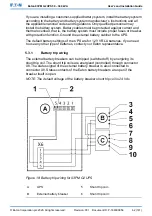


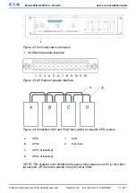


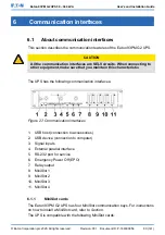


Figure 22: Communication interfaces
1. X9 External parallel interface
Figure 23: X9 External parallel interface
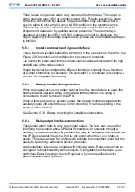
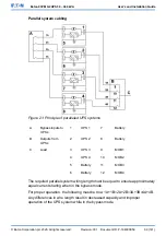
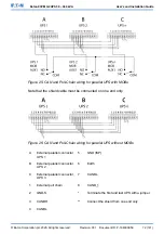
Figure 24: Simplified CAN and Pull-Chain wiring for parallel UPS system
A
UPS 1
1
CAN
B
UPS 2
2
Pull chain
C
UPS 3 (if installed)
D
UPS 4 (if installed)
NOTE: This drawing is for distributed bypass wiring purposes and it is not a floor
layout plan. UPSs can be placed in any physical order.
© Eaton Corporation plc 2020. All rights reserved.
Revision: 001
Document ID: P-164000956
71 (141)
Eaton 93PM G2 UPS 50 – 360 kVA
User’s and Installation Guide